TM 5-3810-294-34
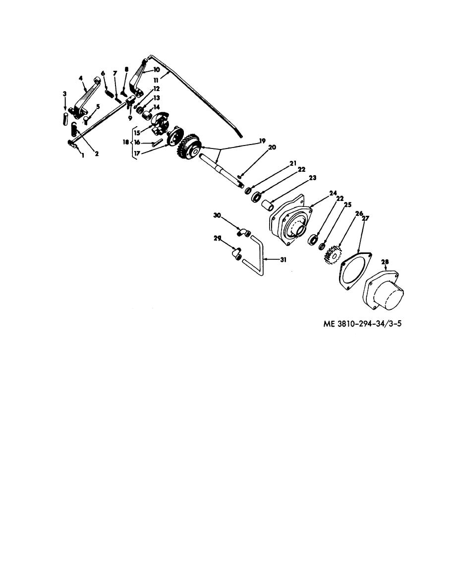
Figure 3-5. Governor, exploded view.
a. Remove drive housing cover (28) and gasket (27)
b. Inspect all parts for wear or damage and replace
from drive housing (24).
with new parts where necessary.
b. Remove step-up (26), key (20) and spacer (25).
c. Be sure that all oil holes and passages are open
Pull out drive shaft (19).
and clean.
c. Remove spacer (23) from drive shaft.
d. Remove any burrs found on the drive gear or shaft
d. Remove stop ring (12), thrust bearing (13) and
with a stone.
thrust sleeve (14) from drive shaft.
3-29. Reassembly
e. The governor carrier (17) and drive gear (19) are
a. Assemble governor weights (15) in carrier (17),
attached to each other with four cap screws and four lock
using two pins (16) and two cotter pins. The pins (16)
washers. Remove the cap screws and governor carrier.
are drilled at one end, and are to be assembled in the
f. Remove cotter pin from weight pins (16) and drive
carrier so the holes will line up to take the cotter pin. Be
out pin to remove the weights.
sure the carrier (17) turns freely when positioned in the
g. Press out the bushings from the drive housing (21)
counterbore of gear (19).
if they need replacing.
b. If inspection proves the drive shaft and gear (19) to
3-28. Cleaning, Inspection and Repair
be in good order (neither are serviced separately),
a.
Clean all parts thoroughly and dry off with
secure governor weight carrier
compressed air.
3-13


