TM 5-3810-294-34
cover (28) with three capscrews to the drive housing
assembly (18) to gear with four cap screws from
(24).
back of the gear.
g. Place thrust sleeve (14) and thrust bearing (13)
c. If bushings (21) are to be replaced with ones,
on the drive end of the shaft. Fit stop ring (12) in the
press them into the drive housing (24) ream the
groove of the shaft.
bushings to .874 - .875 inch.
Note. Lubricate bearing (13) with SAE-30
d. Install spacer (23) and place shaft, as it now
lubricating oil after it is assembled.
assembled, in the drive housing, after first wiping
some SAE-30 lubricating oil on the housing end of
3-30. Installation
the shaft.
Refer to TM 5-3810-294-20 to install and adjust the
e. Install spacer (25), key (20) and gear (26) on
governor assembly.
drive shaft (19).
f. Install a new gasket (27) and drive housing
Section VI. REPAIR OF WATER PUMP
3-31. Description
The water pump is belt driven by the engine fan pulley. It
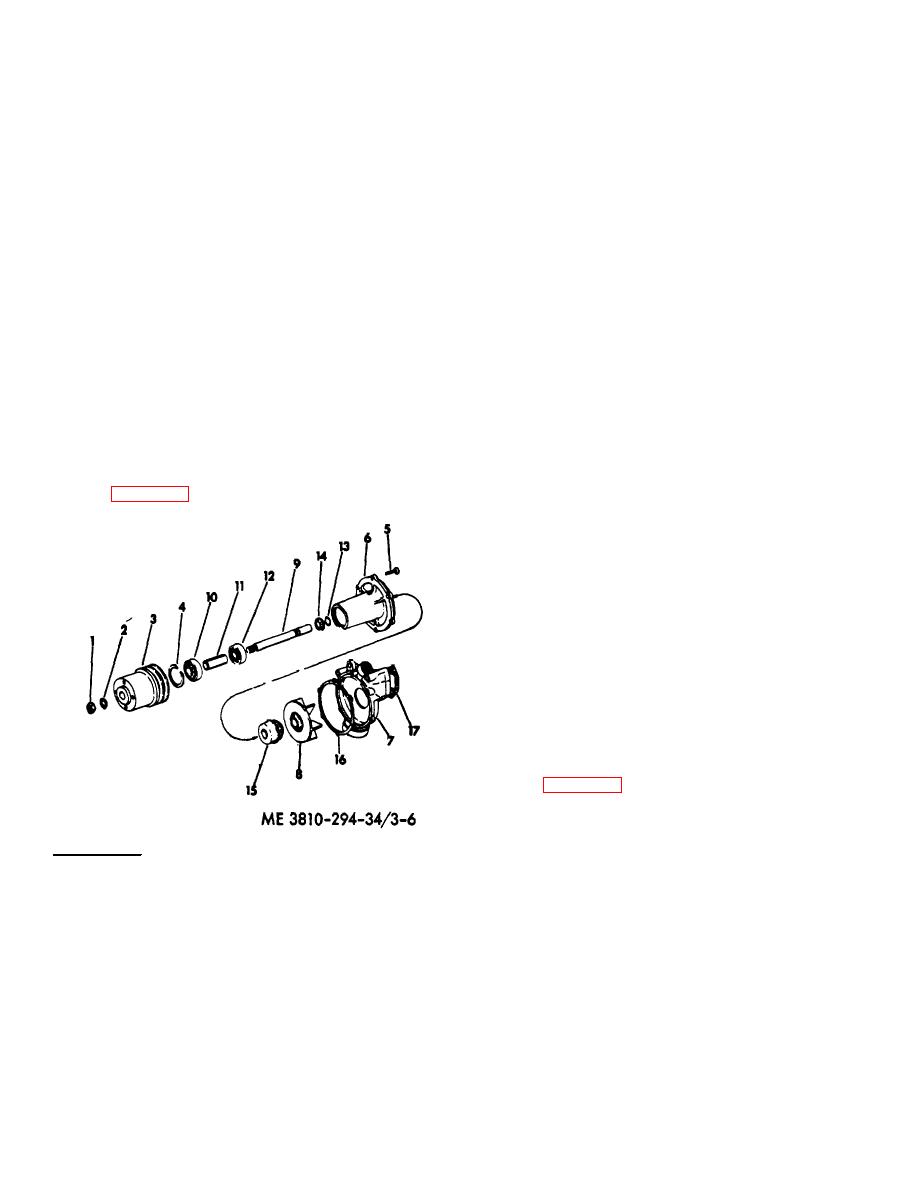
a. Remove the nut (1), washer (2) and press the
consists essentially of a two piece body and a shaft
pulley (3) off the shaft (9).
mounted impeller.
Impeller rotation drives coolant
b. Remove the snap ring (4).
throughout the cooling system by centrifugal force.
c. Remove the bolts (5) and separate the bearing
3-32. Removal
housing (6) from the pump body (7).
Refer to TM 5-3810-294-20 to remove the water pump.
d. Press the shaft (9) out of the impeller (8).
3-33. Disassembly
e. Press off the bearing (10), spacer (11) and bearing
Refer to figure 3-6 and disassemble the water pump as
(12). Remove the lock ring (13) and slinger (14).
follows:
f. Remove the seal (15) from the housing (6) and
remove the gaskets (16 and 17).
3-34. Cleaning
Clean all parts except rubber parts in dry cleaning
solvent (Federal Specification P-S-661) and dry with
compressed air.
3-35. Inspection and Repair
a. Replace the pump seal and gaskets if they are
worn or damaged.
b. Replace the impeller if the seal seat surface is
scored.
c. Replace the bearings if they are worn.
d. Replace the shaft and housings if they are
damaged.
3-36. Reassembly and Installation
Refer to figure 3-6 and reassemble the water pump as
follows:
a. Place the seal (15) in the housing (6).
b. Press the bearing (12), spacer (11) and bearing
(10) onto the shaft (9).
1.
Pully nut
10.
Front bearing
c. Press the shaft (9) with the bearings into the
2.
Pulley washer
11.
Bearing spacer
bearing housing (6). Install the slinger (14), locking (13)
3.
Pump pulley
12.
Rear bearing
and snap ring (4).
4.
Snap ring
13.
Lock ring
d. Press the impeller (8) onto the shaft (9).
5.
Bolt
14.
Slinger
e. Set the gasket (16) in place. Assemble the body
6.
Bearing housing
15.
Seal
(7) to the bearing housing and secure with the bolts (5).
7.
Pump body
16.
Gasket
f. Press the pulley (3) onto the shaft and secure the
8.
Impeller
17.
Gasket
pulley with the washer (2) and nut (1).
9.
Pump shaft
g. Set the gasket (17) in place and install the pump as
outlined in TM 5-3810-294-20.
Figure 3-6. Water pump, exploded view.
3-14


