TM 5-3810-294-34
a. Install throttle lever shaft (27) in cover, hearings
c. Install engine support insulator (12) on engine front
(26), and oil seal (25). Press oil seal (24) in cover.
support (11) and secure support with bolts (9) and lock
b. Assemble gasket (23), plate (22), and gasket (21)
tab (10). Secure gear cover to front support with nuts (7)
on cover (20) and lift into place. Secure into place with
and washer (8).
capscrew (17) and washer (18). Install studs (19 and
d. Install key (5), damper pulley (6), capscrew (3), and
16), and timing indicator (15). Secure timing indicator
lockwasher (4). Secure with crankshaft nut (1) and
with nuts (13) and washer (14).
washer (2).
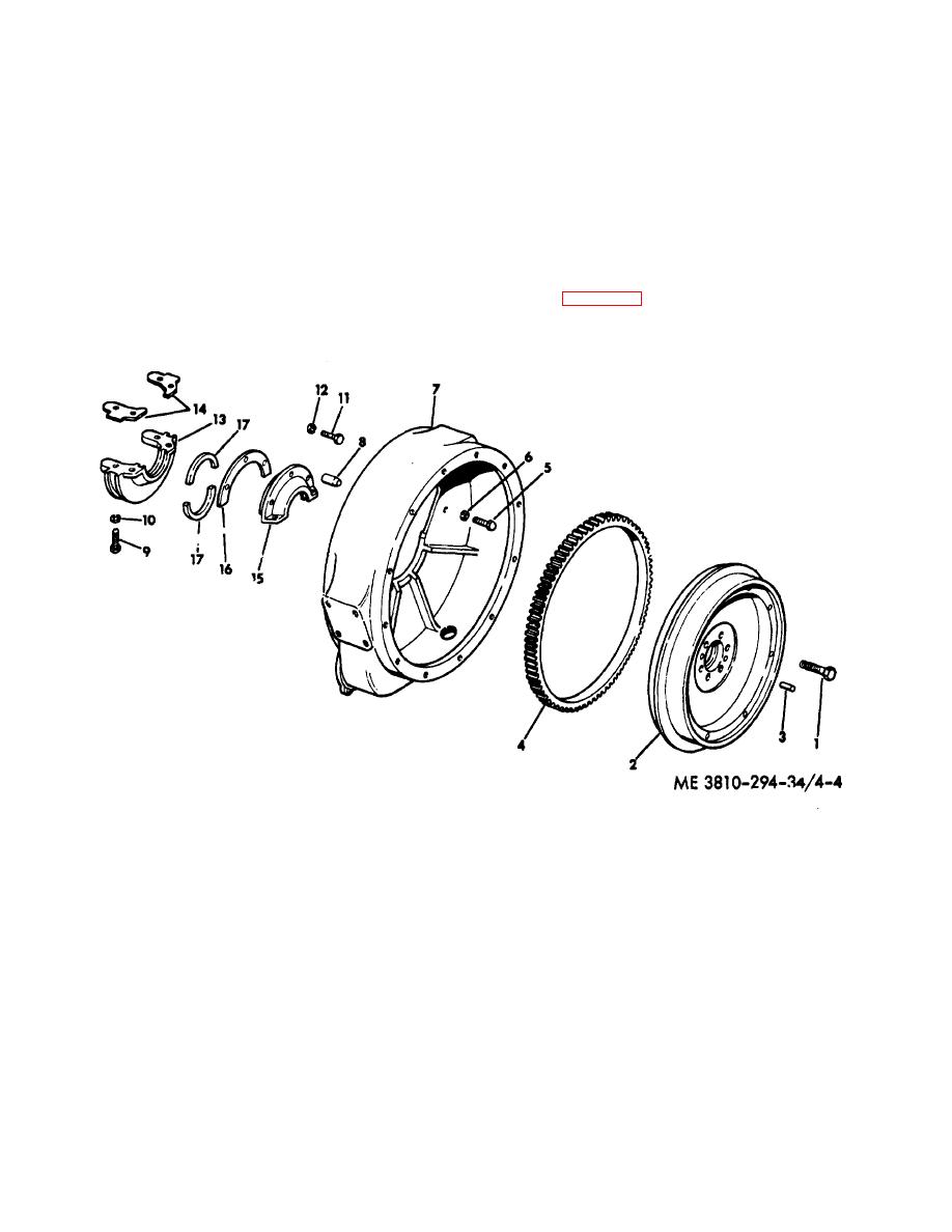
Section IV. REPAIR OF FLYWHEEL AND HOUSING
4-18. Description
4-19. Removal
The flywheel is attached to the rear of the crankshaft. Its
Refer to figure 4-4 and remove capscrew (1). With soft
purpose is to oppose and moderate by its inertia any
hammer, tap on the flywheel to loosen it from the
fluctuations in the speed of the engine.
crankshaft. Set flywheel aside.
1.
Capscrew (6)
10.
Lockwasher (2)
2.
Flywheel
11.
Capscrew (3)
3.
Dowel (2)
12.
Lockwasher (3)
4.
Ring gear
13.
Retainer
5.
Capscrew (6)
14.
Gasket (2)
6.
Lockwasher (6)
15.
Retainer
7.
Flywheel housing
16.
Gasket
8.
Dowel (2)
17.
Felt seal (2)
9.
Capscrew (2)
Figure 4-4. Flywheel and housing, exploded view.
4-6


