TM 5-3810-294-34
e. Install oil screen (10) and pin (9).
b. Install key (19) in drive shaft (20). Press drive
f. Position oil pump mounting gasket (8) over the
gear (18) onto the drive shaft 2 15/16. Inch dimension
mounting holes in the block and lift oil pump into place.
from the top of the gear to the end of the shaft. Lock the
Align pump with block for free movement of oil pump
gear on the shaft with pin (17)
shaft. Secure with capscrews (6) and lockwashers (7).
c. Place idler shaft (16) and idler gear (15) in pump
g. Install gasket (5) and position pan (4) in place,
body (21).
and secure with capscrews (3). Install gasket (2) and
d. Lubricate the gears and cams with engine oil, and
drain plug (1).
install gasket (14) and cover (13) on the pump body and
secure with capscrews (11) and washers
(12).
Section VI. REPAIR OF CRANKSHAFT, CAMSHAFT, AND PISTON RINGS
13-32. Description
a. The camshaft controls the action of the intake
c. The connecting rods are forged steel with bronze
and exhaust valves.
The camshaft bearings are
bushings at the upper ends.
Rod caps are not
pressure lubricated and have oil holes drilled in them.
interchangeable and are numbered for identification. The
These oil holes must be aligned with the holes in the
pistons are aluminum alloy, tin plated with hand ground solid
skirts.
b. The crankshaft is the power linkage between the
13-33. Removal
pistons and the power train. It is counterbalanced; and is
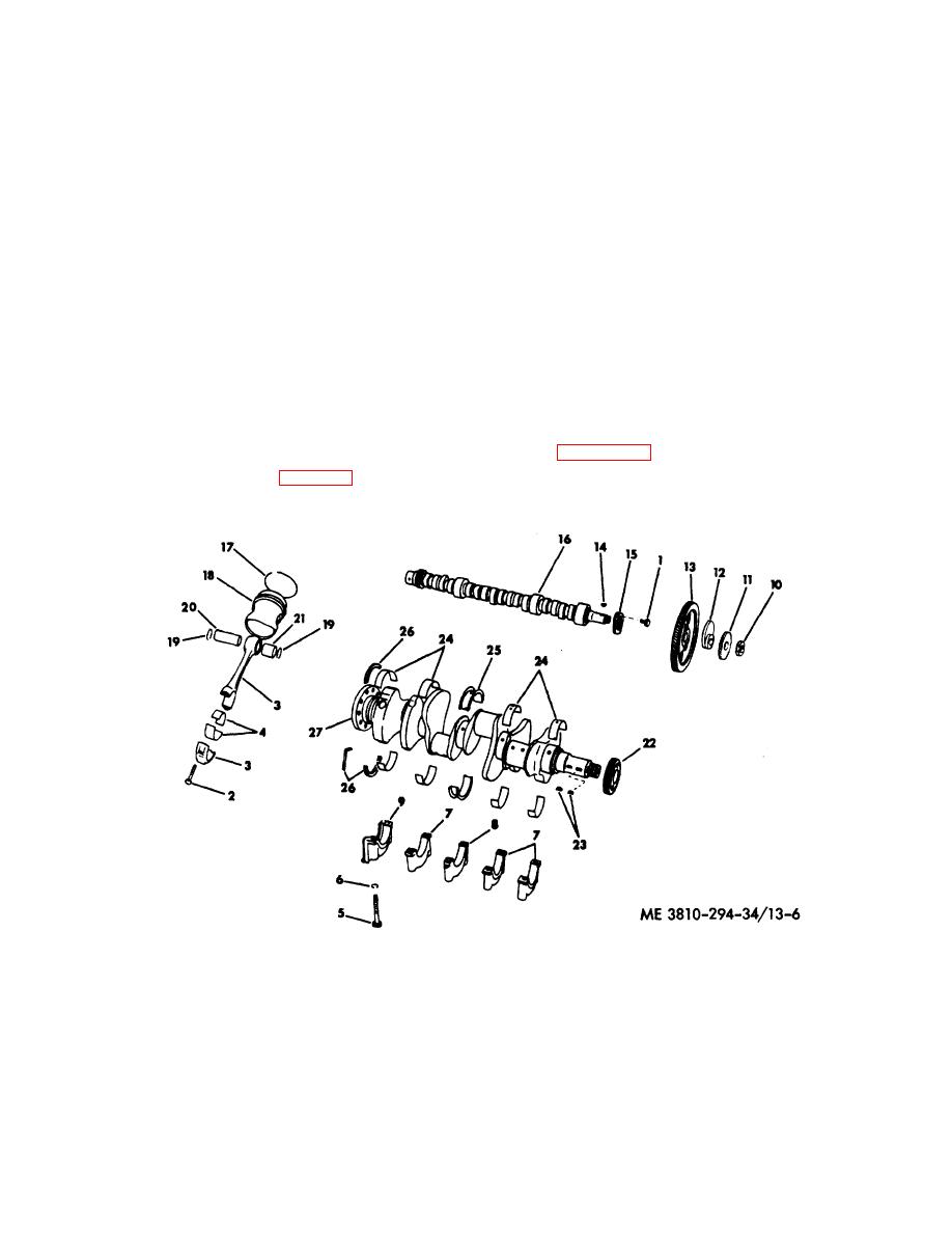
Refer to figure 13-6 and remove camshaft, pistons, and
supported by five steel backed babbitt main bearings.
crankshaft as follows.
The middle bearing, (item25, fig. 13-6) absorbs the
crankshaft end-thrust.
1.
Capscrew (2)
7.
Bearing cap(3)
13.
Gear
19.
Retaining ring(16)
25.
Thrust bearing set (1
2.
Rod bolt (16)
8.
Bearing cap
14.
Key
20.
Piston pin (8)
26.
Seal
3.
Connecting rod (8)
9.
Bearing cap
15.
Thrust plate
21.
Sleeve bearing
27.
Crankshaft
4.
Rod bearing (8)
10.
Jam nut
16.
Camshaft
22.
Crankshaft gear
5.
Bolt (10)
11.
Distributor gear
17.
Piston ring set (8)
23.
Key (2)
6.
Washer (10)
12.
Fuel pump cam
18.
Piston (8)
24.
Bearing set (4)
Figure 13-6. Camshaft, pistons, and crankshaft, exploded view.
13-8
TM 5-3810-294-34


