TM 5-3810-295-34
Section II. REPAIR OF MASTER CYLINDER
7-6.
Description
7-7.
Removal
a. The master cylinder assembly consists of a
Refer to paragraphs 7-2 and 7-3 for removal instructions
reservoir and cylinder assembly. Between the cylinder and
of the maser cylinder.
reservoir there is an intake port and a bypass
7-8.
Disassembly
(compensating) port. Unless actuated, the cylinder is in the
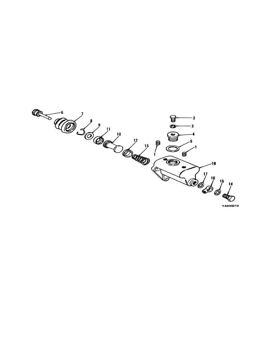
a. Refer to figure 7-2. Remove two plugs (1).
neutral (bypass) position and will allow for temperature
Remove screw (2), gasket (3), filler cap (4) and gasket
expansion or contraction or seepage in the closed hydraulic
(5).
system.
b. Remove link (6) and boot (7). Remove
b. When the cylinder is engaged, the piston move-
retainer (8) and slide washer (9) cups (11) and (12),
ment seals off the bypass port and forces fluid into the
piston (10) and spring (13) out of housing (18)
line. The fluid movement builds pressure in the line
c. Remove bolt (14 gaskets (15) and (17), and
and will actuate the hydraulic cylinder at the appropriate
fitting (16).
brake or clutch.
1
Pipe plug (2)
10
Piston
2
Cap screw
11
Cup
3
Gasket
12
Cup
4
Filler cap
13
Spring
5
Gasket
14
Bolt
6
Link
15
Gasket
7
Boot
16
Fitting
8
Retainer
17
Gasket
9
Washer
18
Housing
Figure 7-2. Master cylinder assembly--exploded view.
7-9.
Cleaning, Inspection and Repair
immerse parts in hydraulic fluid (me type used in
a. Clean housing and all other metal parts with
system) to remove all traces of cleaning solvent. Dry
suitable cleaning solvent, such as Federal Specification
parts with compressed air or a clean, dry, lint-free
P-D-680 or equivalent. Immediately after cleaning,
cloth after cleaning.
7-3


