TM 5-3810-295-34
Check for leaks. Discard parts as necessary.
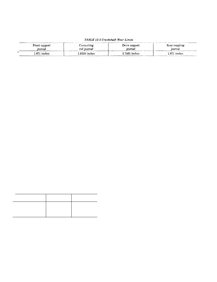
k. Check for scratches, scoring and wear of the
(4) Release pressure from inlet and remove plug
crankshaft. Replace if wear limits of table 13-3 are not
from water outlet. Replace water outlet fitting.
met.
13-30. Reassembly and Installation
L Check front support for scratches, scoring and
a Refer to figure 13-8 and reassemble the air com-
wear. If thrust flange measurement exceeds 1.7555 in-
pressor as follows;
ches, replace.
(1) Replace name plate (72) with drive screws (71)
m. Check ID of support bearing if measurement ex-
if required.
ceeds 1.7555 inches, replace bushing.
(2) Lubricate bushing bore in crankcase (69).
r Check ID of connecting rod bearings. If ID ex-
Press new bushing (70) into bore flush with bore sur-
ceeds 1.9395 inches at crankshaft end or at piston pin
face.
end, connecting rod must be scrapped.
(3) Assemble piston (65) and connecting rod (68)
a Check connecting rod for bend and twist. Bend
in the following method.
must not exceed 0.002 inch or twist 0.004 inch.
(a) Heat piston (65) in hot water for 30 minutes,
p. Check gear and drive adapter for excessive wear,
expanding piston pin bore.
broken or cracked teeth and drive spline in adapter.
CAUTION
9 Check OD of piston pin. If OD is worn smaller
Piston pin (67) must not be driven into piston
than 0.6872 inch, pin should be replaced.
pin bore. Driving piston pin into bore will dis-
Inspect piston for scoring, cracks, wear or other
tort piston (65).
damage. Check wear as follows.
(b) Install piston pin (67) through piston (65)
(1) Measure piston wear one inch below and at
and connecting rod (68).
right angle to the piston pin bore. If skin diameter is
(c) Secure piston pin (67) with retaining rings
less than 3.6165 inches at 70F, discard piston.
(66).
(2) Measure piston pin bore at 70F. If ID of bore
(4) Assemble piston rings (62, 63 and 64) on
is greater than 0.6885 inch, replace piston.
piston (65). Install new teflon compression ring (62) in
(3) Install a new ring in groove of piston. Insert a
top groove with inner and outer ring 180 apart. Stag-
0.004-inch feeler gauge between ring and piston
ger gaps on rings (63 and 64).
groove. Compress ring in groove. If ring is below piston
land surface with feeler gauge in place, wear is ex-
CAUTION
cessive and piston must be replaced.
The word "TOP" on compression rings must
s. Check piston ring gaps as follows.
be up (toward crown of piston). Do not scratch
(1) Using a piston head, seat one ring at a time
piston when installing rings. Do not clamp rod
squarely in an unworn portion of cylinder bore.
in vise unless rod is protected by soft wood.
(2) Measure ring gap with a feeler gauge. Gap re-
(5) Lubricate crankcase bore and piston rings. In-
quirement for each ring is shown in table 13-4.
stall piston and rod assembly in crankcase (69) using a
Table 13-4 Ring Gap Requirement
suitable ring compressor.
(6) Assemble pipe plug (61) in crankshaft (60).
Lubricate journals of crankshaft (60).
Ring
Min.
Max.
CAUTION
Support crankshaft (60) with a suitable sup-
No. 1 Compression
0.010 inch
0.020 inch
port block. Do not allow crankcase to rest on
No 2 Compression
0.01O inch
0.020 inch
table.
0.1 Ring
0.0olinch
0.055 inch
(7) Install crankshaft (60) through connecting rod
t Check crankcase cylinder bore for out-of-round-
(68) and bushing (70).
ness and wear with a dial bore gauge. Using 150 grit
(8) Place gasket (59) in place and slide support
stone, bore and hone cylinder bore to accommodate
(57) over crankshaft. Secure with lock plate (56),
0.010-, 0.020-, or 0.030-inch oversized rings if:
washers (55) and capscrews (54) and (53). Torque
(1) Out-of-roundness exceeds 0.0015 inch.
capscrews alternately to 30 ft-lbs. (41 N m).
(2) Bore is worn beyond 3.6285 inches.
(9) Install drive gear key (52) in crankshaft (60).
u Check crankcase bushing in crankcase. If worn
larger than 7.8780 inches, replace bushing.
13-20


