TM 5-3810-295-34
is improper, loosen retainer and rotate cup one-quarter
freely. If any restriction is felt, pin should be removed
turn and retorque retainer to 50 ft-lb (68 N. ‡ m).
and a new pin installed.
(5) Repeat paragraphs (2), (3), and (4) above
Repeat as necessary.
to assemble roller (16), pin (15), and lockwire (14) to
(8) Remove plunger and lubricate with test oil.
valve tappet body (13).
Install spring (23) on plunger and insert into adapter.
14-15. Installation
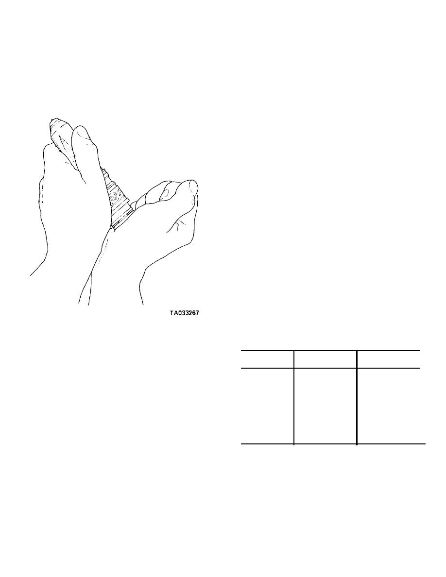
(9) Check cup spray pattern by removing
a. Refer to figure 14-8. Install spring clips (6) and
plunger and spring and fill barrel and cup full of fuel oil.
(7) on all tappets except injector tappets used at No. 2
Insert plunger, less spring, into injector forcing fuel out
and No. 6 cylinders.
spray holes (fig. 14-11).
CAUTION
Spring clip must not be on tappets No. 2 and
No. 6 when checking injection timing.
b. Dip tappet rollers (11) and (16) in clean engine
oil and install valve and injector tappets in tappet bores
of block.
c Hold tappet plate (5) across tappet and tap
lightly with a soft headed hammer to align tappets.
d. Place feeler gauge on shim between tappet plate
on both sides of injector tappet to maintain a 0.010
inch (minimum) clearance, tighten capscrews to 18 to
22 ft-lb (24-30 N ‡ m) torque.
NOTE
Valve tappets may have 0.010- to 0.030-inch
clearance between plate and tappet, if re-
quired, to maintain the 0.010-inch minimum
clearance between injector tappets and plate.
e. Install cylinder head per paragraph 14-21 if
removed.
f. Install injector push rod (2) in No. 2 cylinder on
right bank and No. 6 on left bank.
g. Using an approved timing fixture check injection
timing. Timing may be advanced or retarded by
changing camshaft key. If timing check shows a timing
change is desirable, select next advance or retard key
Figure 14- 11. Checking open cup spray holes.
from listing in table 14-1.
WARNING
Table 14.1 Camshaft Key Data
Any time fuel is forced from cup spray holes
Key
Amount of
Degrees
be sure to keep hands or body out of spray
part No.
offset (inch)
changed
stream to prevent injury.
S-302
0.000
0
(10) Remove plunger and reinstall spring.
200711
0.007
0.5 Advance
(11) Lubricate and install new preformed
200709
0.015
1.0 Advance
packing (24, fig. 14-8) and (25) into proper grooves in
200708
0.023
1.5 Advance
adapter.
20079
0.015
1.0 Retard
(12) Install new fuel screen (27) and retainer
200708
0.023
1.5 Retard
(26).
200714
0.039
2.5 Retard
(13) Place injector assembly in a clean area until
216294
0.0035
0.18
ready to leak test and use.
216782
0.011
0.75
b. Reassemble tappet assembly in the following
method. (See fig. 14-8.)
h. Remove injector tappets used to check injection
(1) Press new insert (12) in tappet body (8),
timing and install new spring clip (7).
being sure insert is securely seated. Tappet body must
i. Lubricate preformed packing with clean oil.
be supported in a manner not to spring the tappet forks.
Lower injector assembly into head. Align injector so
(2) Place tappet body in a V-block with the
screen is toward center vee.
lockwire side up.
j. With a clean blunt object on injector body, "seat"
(3) Place new roller (11) in tappet body. Install
injectors by giving a quick hard push. A" snap" should
lockwire (9) in roller pin (10). With a 0.006-inch shim or
be heard and felt as cup seats in head.
feeler gauge between side of roller and tappet fork,
k. Install links (21), spacers (20), clamp (19),
press pin (10) in tappet body through roller (11).
washers (18) and screws (17).
(4) Remove shim and check that roller rotates
14-11


