TM 5-381 0-295-34
b. Press brake shoe bushing (6) from brake shoe. If
and wear. Replace lining if saturated with grease or
inside diameter of bushing (6) exceeds 1.513 inch, the
oil. If linings are worn to within one-sixteenth of an
bushing should be replaced.
inch of bolt heads, replace linings.
c. Remove cotter pin (7), washer (8), nut (9), washer
NOTE
(10) and spring pin (11).
When replacing brake linings, replace all lin-
d. Using a suitable punch, drive out roll pins (12)
ings on both sides of the axle.
and (13), and roller pin (14). Remove cam roller (15).
c. Check bushing (6). If inside diameter exceeds
e. Remove brake shoe linings by removing plugs (16),
1.513 inch, replace the bushing.
nuts (17), washer (18), and bolts (19). Remove lining
16-22. Reassembly
(20) from shoe (21).
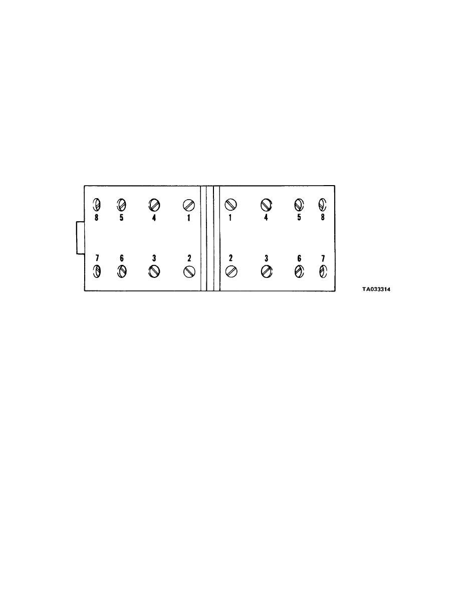
a. Install brake linings (20) on shoe (21) and secure
16-21. Cleaning, Inspection and Repair
with bolts (19), washers (18) and nuts (17). Tighten
a. Clean all metal parts in cleaning solvent, Federal
nuts to 1618 ft-lb (21.7--24.4 N . m), in the sequence
Specification P-D-680, or equivalent before inspecting.
shown in figure 16-7. Install linings plugs (16).
b. Check brake lining for oil or grease saturation
Figure 16-7. Brake lining installation.
b. Position brake cam roller (15) on brake shoe. Ap-
with washer (10) and nut (9). Install washer (8) and cot-
ply a light coating of lithium base grease (wheel bear-
ter pin (7).
ing grease) on roller pin (14) and insert pin. Secure
16-23. Installation
with roll pins (12) and (13).
Refer to figures 16-5 and 16-2 and install brake shoe
c. Press brake shoe bushings (6) into the brake shoe.
assembly. Refer to chapter 16, sections I and II, and as-
d. Install spring pin (11) in brake shoe and secure
semble axle parts and install wheel and tire assembly.
16-15/(16-16 blank)


