TM 5-3810-295-34
19-29. Cleaning, Inspection and Repair
(2) Reinstall all hydraulic lines to the hydraulic
a. Clean all metal parts in cleaning solvent, (Fed.
cylinder.
Spec. P-D-680, or equivalent) and dry thoroughly.
19-30.1. Control Valve, Outrigger
b Inspect rod, pistons and cylinder shell for
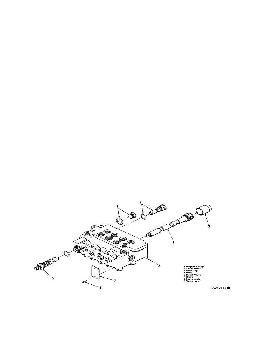
a. Refer to figure 19-12.1 and remove the control
cracks, scoring or excessive wear. Repair or
valve as follows:
replace defective parts.
(1) Remove and cap all hydraulic lines to the
c. Replace all packings and seals.
control valve.
19-30. Reassembly and Installation
(2) Remove mounting hardware and lift control
a.Rer to figure 19-12 and reassemble the blade
valve from vehicle.
hydraulic cylinder as follows:
b. Refer to figure 19-12.1 and disassemble the
(1) Install ring (17), packing (16), retainer (15),
control valve as follows:
packing (14), ring (13), bushing (12), and packing
(1) Remove plug and body (I) from valve body (8).
assembly (11) into cylinder shell (18).
(2) Remove check valve and ring (2) from valve
(2) Install piston half (5), packing (8), nylon rider
body.
(6), packing assembly (7), and piston half (9) on
(3) Remove spool cap (3) and spool (4) from
piston rod (10).
control valve
(3) Install the remaining packing (8), packing
(4) Remove relief valve and ring (5) from valve
assembly (7), nylon rider (6) and piston half (5) on
body (8).
the piston rod.
a Cleaning, Inspection and Repair.
(4) Install nut (4) on piston rod (10) and torque
(I) Clean all metalic parts with cleaning solvent
to 600--700 ft-lb (813.5--949.1 N. m).
(Fed Spec P-D-680, or equivalent) and dry thoroughly.
(5) Place wiper ring (3) in end cap (2) and install
(2) Inspect for cracks, breaks, stripped threads,
end cap (2) in cylinder (18). Torque the end cap to
corrosion or other defects
10-12 ft-lb (13.6--16.3 N. m).
(3) Replace all gaskets, packing and defective
(6) Install setscrew (1) in end cap (2).
parts.
b.
Install the blade hydraulic cylinder as
d. Refer to figure 19-1 2.1 and reassemble control
described in the following.
valve as follows:
(1) Refer to paragraph 19-27a (4) through (6)
(1) Install relief valve and ring (5) into valve body
and install cylinder to carrier.
(8).
(2) Install spool cap (3) and spool (4) into valve
body (8).
(3) Install check valve and ring (2) into valve body.
(4) Install plug and body (1) into valve body.
Figure 19-13. Control Valve, Outrigger
Change 1 19-21


