TM 5-3810-295-34
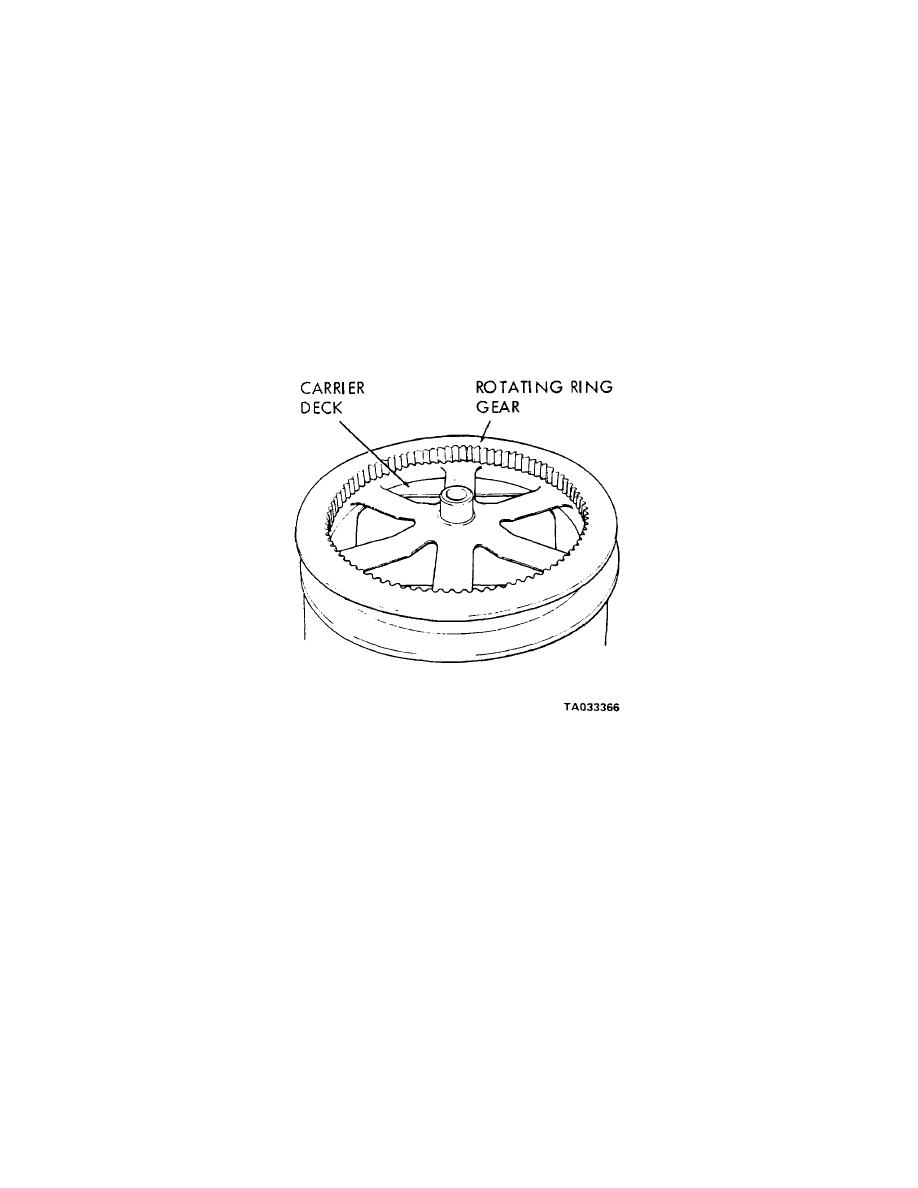
Section X. REPAIR OF ROTATING RING GEAR
19-35. General
19-37. Cleaning, Inspection and Repair
The crane assembly rotating gear and rollers
a. Clean all parts with cleaning solvent (Fed.
operate on a dual flanged center, hub-type ring
Spec.
gear. This ring gear is bolted to the carrier frame to
P-D-680, or equivalent) and dry thoroughly.
serve as the swing or tracking gear for the crane
b. Inspect all parts for excessive wear and
assembly.
damage.
19-36. Removal
c. Replace all damaged or defective parts.
a. Remove the crane assembly tpara 2-18).
19-38. Installation (fig. 19-14)
b. Remove mounting capscrews.
a. Using a suitable lifting device, position the ring
c Using a suitable lifting device, lift ring gear from
gear properly on the carrier frame.
the carrier frame and place on blocks.
b. Install mounting capscrews.
Figure 19-14. Rotating ring gear, removal and installation.
Section XI. REPAIR OF CARRIER FRAME ASSEMBLY
19-39. General
(3) Remove the rotating gear (para 19-36).
The carrier frame is an all weld-steel structure with
(4) Remove the utility blade assembly (para 19-25).
crossmembers,
supporting
brackets
welded
(5) Remove all major assembles and subassemblies
integrally with the frame.
The carrier frame
as described in TM 5-3810-295-12 and this manual.
supports and caries the crane and all components.
b. Refer to figure 19-15 and disassemble the carrier
19-40. Removal and Disassembly
frame as follows:
a. Remove the carrier frame as described as
(1) If necessary, remove screws (1) and damaged
follows:
plates (2, 3 and 4).
(I) Remove the crane assembly (para 2-18).
(2) Remove the carrier engine assembly (para
12-6).
Change 1 19-23


