
TM 5-3810-300-24&P-3
Fuel Injector
2.1.1
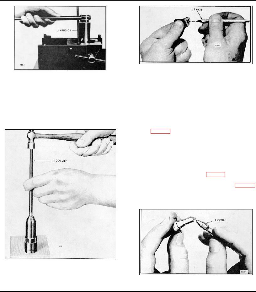
Fig. 27 - Cleaning Injector Spray Tip
Fig. 25 - Removing Injector Nut
Any injector which is disassembled and rebuilt must be
tested again before being placed in service.
each cylinder at a given throttle setting, thus resulting in
a smooth running, well balanced engine.
Disassemble Injector
An injector which passes all of the above tests may be
put back into service. However, an injector which fails to
If required, disassemble an injector as follows:
pass one or more of the tests must be rebuilt and
checked on the calibrator.
1. Support the injector upright in injector holding fixture J
22396 (Fig. 23) and remove the filter caps, gaskets and
filters.
NOTE: Whenever a fuel injector is
disassembled, discard the filters and
gaskets and replace with new filters and
gaskets. In the offset injector, a filter is
used in the inlet side only. No filter is
required in the outlet side (Fig. 34).
2. Compress the follower spring as shown in Fig. 11.
Then raise the spring above the stop pin with a screw
driver and withdraw the pin. Allow the spring to rise
gradually.
Fig. 26 - Removing Spray Tip from Injector Nut
Fig. 28 - Cleaning Spray Tip Orifices
Page 14
Page 170