TM 5-3810-300-24&P-3
Fuel Injector
2.1.1
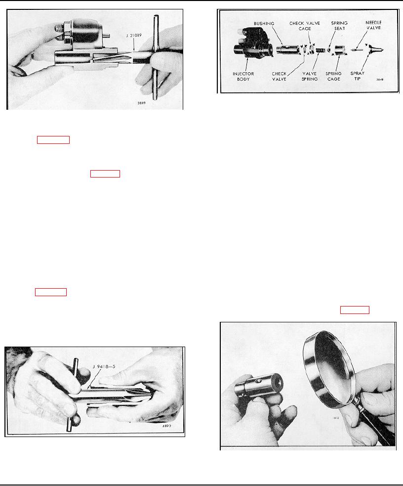
Fig. 31 - Sealing Surfaces which may Require Lapping
Fig. 29 - Cleaning Injector Body Ring
8. Withdraw the injector control rack from the injector
body. Also remove the seal ring from the body.
3. Refer to Fig. 24 and remove the plunger follower,
plunger and spring as an assembly.
Clean Injector Parts
4. Invert the fixture and, using socket J 4983-01, loosen
Since most injector difficulties are the result of dirt
the nut on the injector body (Fig. 25).
particles, it is essential that a clean area be provided on
which to place the injector parts after cleaning and
5. Lift the injector nut straight up, being careful not to
inspection.
dislodge the spray tip and valve parts. Remove the
spray tip and valve parts from the bushing and place
Wash all of the parts with clean fuel oil or a suitable
them in a clean receptacle until ready for assembly.
cleaning solvent and dry them with clean, filtered
compressed air. Do not use waste or rags for cleaning
When an injector has been in use for some time, the
purposes. Clean out all of the passages, drilled holes
spray tip, even though clean on the outside, may not be
and slots in all of the injector parts.
pushed readily from the nut with the fingers. In this
event, support the nut on a wood block and drive the tip
Carbon on the inside of the spray tip may be loosened
down through the nut, using tool J 1291-02 as shown in
for easy removal by soaking for approximately 15
Fig. 26.
minutes in a suitable solution prior to the external
cleaning and buffing operation. Methyl Ethyl Ketone J
6. Refer to Fig. 36 and remove the spill deflector. Then
8257 solution is recommended for this purpose.
lift the bushing straight out of the injector body.
Clean the spray tip with tool J 9464-01 (Fig. 27).
7. Remove the injector body from the holding fixture.
Turn the body upside down and catch the gear retainer
and gear in your hand as they fall out of the body.
Fig. 30 - Cleaning Injector Nut Spray Tip Seat
Fig 32 - Examining Sealing Surface with a Magnifying
Glass
Page 171

