DRUM PAWLS
SUBSECTION 7E
When the pawl switch is in the ON position hydraulic pres-
sure is released from the cylinder and the spring engages
the pawl in the drum ratchet, When the switch is OFF,
hydraulic pressure overcomes the spring tension and
releases the pawl.
REMOVAL AND INSTALLATION. If upon inspection, it is
revealed the pawl is damaged in any way, the pawl must be
replaced. Also, if the hydraulic cylinder does not function as
described above, it must be replaced with a new one. To
replace either or both of these items, proceed as follows:
1. Start the engine and lower the hook block, or any lifting
device that may be connected to the left and right main
drum, to the ground.
2. Render the machine inoperable by disconnecting the
ground cable to the battery.
3. To change the pawl, proceed as follows (see Figure
7E-1):
A. Loosen jam nuts (15) and release tension in spring (18).
Figure 7E-2. Drum Pawls (2100J1320-1)
Remove spring (18). Disconnect hydraulic cylinder cle-
vis (05) from pawl (01 or 02).
1. Engage the pawls into the drum teeth.
B. Remove cotter pin (04) and washer (03). Remove pawl
2. Check both pawls for complete engagement to the drum
(01 or 02) and install a new pawl, washersand cotter pin
teeth.
(04).
NOTE
C. Install clevis (05) to pawl. Connect spring (18) to the
pawl and adjust the pawl as explained later.
It may be necessary to push the drum control levers to
the "lower" position momentarily to enage the pawls
4. To replace hydraulic cylinder (07), proceed as follows:
in the drum teeth.
A. Move the drum pawl switch to the OFF position. Make
3. Release the left and right drum pawl switches and allow
sure all hydraulic pressure is released from the cylinder.
them to return to the OFF position and pull the drum control
Disconnect the hydraulic lines from cylinder (07).
levers to the "raise" position momentarily to disengage the
B. Remove clevis (05) from pawl and remove cylinder (07)
pawls from the drum teeth.
from mounting bracket (10).
4. Check both pawls for complete release from the drum
C. Remove clevis (05) and nut (06) from cylinder (07) and
ratchet teeth.
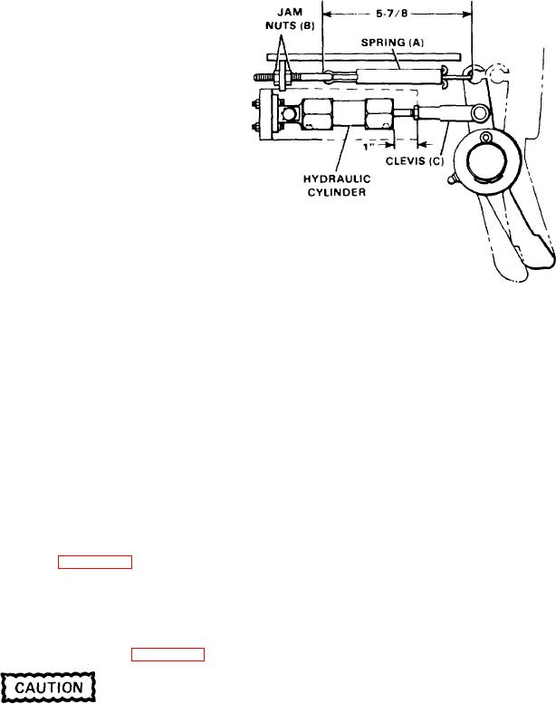
install on new cylinder. See Figure 7E-2 and set clevis
5. If the pawls do not operate properly, proceed as follows:
distance to 1" dimension shown. Tighten nut (06).
A. Repeat steps 1 and 2.
D. Install cylinder (07) on mounting bracket (10) and install
clevis (05) on pawl. Adjust pawl as explained below.
B. The length of pawl spring (A) should be 5-7/8" and the
pawls must be fully engaged in the drum ratchet teeth.
ADJUSTMENT. To adjust the pawl after pawl and/or
C. If the spring is not the dimension given in step B, adjust
cylinder replacement, proceed as follows (see Figure 7E-2):
to 5-7/8" using jam nuts (B).
D. The pawls should be disengaged from the drum teeth by
a minimum of 1/4" when the pawl is disengaged. If
The following procedure must be done very
necessary adjust clevis (C) and jam nut (D) to get the
carefully to arrive at the right settings. If not
pawl to disengage from the drum teeth.
correct, serious damage could result to the
6. As a final check, repeat steps 1 through 4.
machine when operated.
7E-2

