
PROPEL GEAR CASE
SUBSECTION 9D
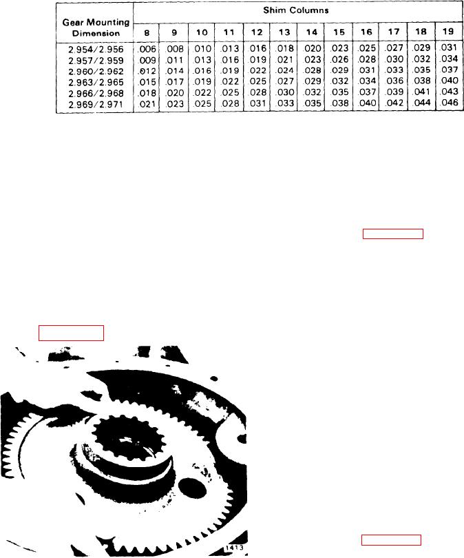
Table 9D-5. Shim Spacing
42. Coat O-ring (14) with grease and install it on the input
36. Install the cover, capscrews, and lockwashers and
housing.
tighten to 80-90 ft-lbs.
43. Place the input housing on ring gear (13) making sure
37. Coat O-ring (61) with grease and install it on shaft (62).
that the pilot of the input housing seats in the counterbore
38. Install the shaft and O-ring into the input housing.
of the ring gear.
39. Install the bearings and bull gear on shaft (62) as fol-
44. Install capscrews (59) and lockwashers (58) and
lows:
tighten to 160-180 ft-lbs.
A. Press bearing cone (55) with the small diameter out onto
CENTER SECTION. To assemble the center section, pro-
shaft (62).
ceed as follows (see Figure 9D-12):
B. Press bearing cups (51) into the bore of bull gear (49)
1. Install sun gear (15) and snap ring (17) into input planet
carrier (16). Install input planet gears (20), washers (19).
C. Place spacers (43 and 52) into the bore of the bull gear
shafts (22). and bearings (21) into the input carrier.
D. Press the remaining bearing cup into the bore of the bull
NOTE
gear.
It is important that these items be installed in their
E. Install cone spacer (53) onto shaft (62)
original positron and location.
F. Install the bull gear over the bearing cone on the shaft
2. Drive steel roll pins (23) flush with the carrrer, locking
[see Figure 9D-11).
the shafts in place.
3. Install the planet assembly into the gear case with sun
gear (15) up.
4. Install carrrer spacer (12) onto planet carrier (16)
5. Install planet gears (09) and bronze shafts (10) into out-
put planet carrier (08).
NOTE
It is important that the pins and gears be installed in
their original positions and locations.
6. Drive roll pins (07) into the carrier and shafts.
7. Use the tapped holes in the carrier and install the carrier
assembly into ring gear (13).
OUTPUT SECTION. To assemble the output section, pro-
ceed as follows (see Figure 9D-12):
1. Install seal (01) into the front of cover (04).
2. With the center section resting on the input side, place
Figure 9D-11 Bull Gear lnstallation
output shaft (06). with spacer (36) adjacent to collar, into the
spline in output carrier (08).
G. Press the remaining bearing cone onto shaft (62) with
3. Place the cover assembly over the output shaft, being
the small drameter down.
careful not to damage seal (01). Check to insure that the
pilot of the cover has sealed properly into the ring gear bore.
40. Place cap (48) behind the bearing cone.
4. Install capscrews and lockwashers (02 and 03) and
41. Secure with three capscrews (47) torqued to 80-90 ft-
torque to 160-180 ft-lbs.
Ibs Lockwire the capscrews.
9D-6