
SUBSECTION 9E
CRAWLER COMPONENTS
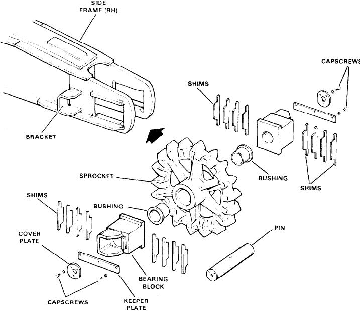
Figure 9E-3. Idler Sprocket (2100J968)
5. Remove the bearing block from the side frame and in-
1. Remove the track as described earlier in this subsec-
tion.
spect for wear or damage.
2. Drain the oil from the propel driveshaft. Replace the
6. Remove the bushings if bushing replacement is neces-
sary. The bushings should be replaced if worn excessively
drain plug.
or deeply scratched.
3. Remove the propel gear case. See Subsection 9D.
ASSEMBLY AND INSTALLATION. To install the crawler
4. Jack the machine at the corner of the carbody nearest
idler shaft, reverse the above procedure and adjust the
the drive sprocket to be removed. Use suitable blocking
crawler track as explained earlier. When assembling, pay
beneath the jacks to support the weight of the machine on
particular attention to the bushings to see that they are
the jack.
properly installed. Lubricate all parts during assembly.
5. Block the sprocket to prevent it from falling while the
driveshaft is being removed. The sprocket weighs about
DRIVE SPROCKET ASSEMBLY (2100J969)
430 Ibs.
REMOVAL AND DISASSEMBLY To remove and disassem-
6. Remove capscrews (01 and 16) and retainer (15). Also,
ble the drive sprocket assembly, proceed as follows (see Fig-
remove capscrews (19) and end plate (18).
ure 9E-4):