
CRAWLER COMPONENTS
SUBSECTION 9E
cable over the top of the crawler side frame and attach it to a
CRAWLER TRACK REMOVAL
pulling device. Propel the machine forward while keeping
AND INSTALLATION
the cable taut. Make sure the shoe engages the rollers.
REMOVAL. To remove the track, proceed as follows:
2. Continue this operation until the shoe is over the top of
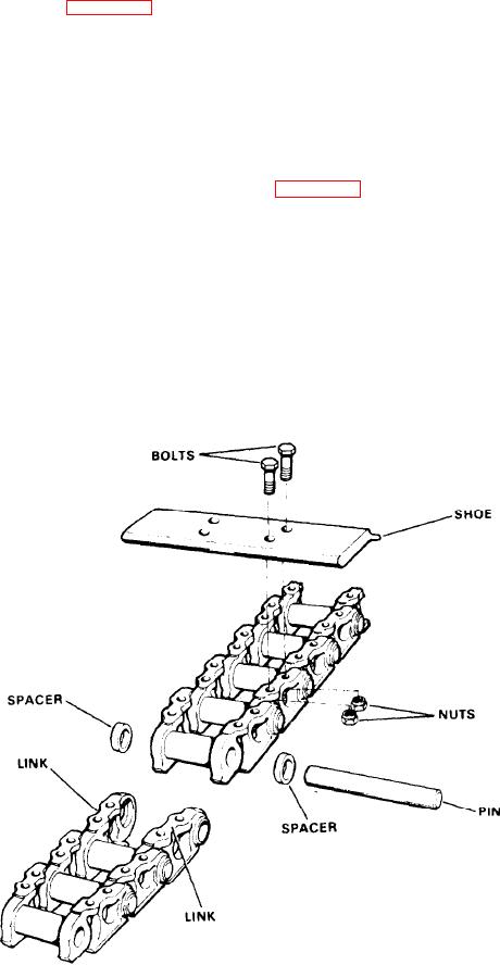
1. Propel the machine to place the master track link (the
the idler shaft. Remove the bar and cables.
one with the longer pin) in position above the vertical
3. Using a suitable lifting device, lift the lower shoe portion
centerline of the idler shaft (see Figure 9E-2).
and align the holes in the two shoes.
2. Loosen the track tension by removing the shims behind
4. Drive the master pin into the two shoes until the pin is
the bearing block of the idler shaft.
centered.
3. Drive out the master link pin in the track shoe and propel
the machine to the rear until the track is laid out flat. Do not
5. Adjust the track tension.
propel the machine forward, since the crawler track will
IDLER SPROCKET ASSEMBLY (2100J968)
bunch up and may cause damage to the machine. Propel
backwards until the track is free of the crawler tumbler on
REMOVAL AND DISASSEMBLY. If it is necessary to re-
the rear. Then jack up the carbody and pull the track out
move the idler sprocket assembly, proceed as follows (see
from under the crawler side frame.
TRACK REPAIRS. Repairs are limited to the replacement of
1. Remove the crawler track as explained earlier in this
individual parts. If the crawler has been adjusted to the
subsection.
point where no more slack can be taken up, a crawler shoe
2. Place a jack beneath the axle at the corner of the car-
will have to be removed. If this is the case, it is important
body nearest the idler shaft to be removed. Use suitable
that this is done to both crawlers or there will be uneven
blocking beneath the jack to support the weight of the ma-
propel motion.
chine on the jack.
INSTALLATION. To install the track, proceed as follows:
3. Remove the keeper plate, shims and end cap.
4. Support the sprocket with a suitable lifting device (the
1. Place the track under the crawler side frame and lower
sprocket weighs approximately 600 pounds) and drive the
the machine onto the track. Insert a bar through the holes in
shaft out. Lift the sprocket out of the side frame.
the shoe and attach a cable to each end of the bar. Run the
Figure 9E-2. Crawler Track