
Remove and Install Blower Drive Shaft
If the blower drive shaft is not broken,
i t may be removed as follows:
1. Remove the six bolts (94 and 95) that
secure the flywheel housing small hole
cover (92, Figure 11B-169).
to Figure 11B-172 on page
2. Refer
11B-113 and remove the snap ring and
pull the blower drive shaft out of the
drive assembly.
NOTE
Some shafts have a tapped hole in
the end which can be used as an
aid in removing the shaft.
If the blower drive shaft is broken and it
is
not
possible
to
remove
all
of
the
pieces, it will be necessary to remove the
blower, see Subsection 11D.
A broken drive shaft indicates an unusu-
al loading which may have been caused
other
failure
bearing
by
a
I n s p e c t t h e blower d r i v e ,
malfunction.
blower rotors and the housing before re-
placing the drive shaft. See the blower
i n s p e c t i o n p r o c e d u r e i n S u b s e c t i o n 11D.
Reverse the removal steps to install the
blower drive shaft.
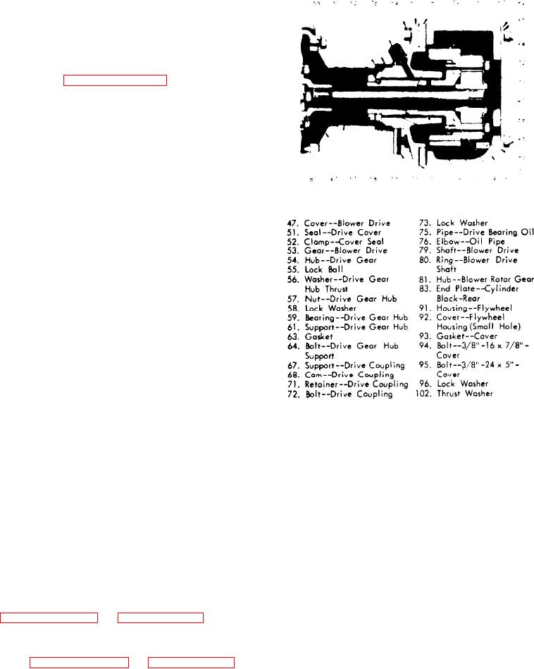
F i g u r e 11B-169. Blower Drive Gear
a n d Support
Remove Blower Drive Gear (Flywheel
H o u s i n g Removed)
5. Loosen the blower drive support by
tapping it lightly and withdraw the sup-
Removal of the flywheel housing is not
port from the cylinder block rear end
removing the blower
necessary when
Take care to prevent damage to
plate.
drive gear, however, an inspection of
the blower drive gear teeth. Discard the
the gear train is advisable when any one
gasket.
of the gears requires service.
Before removing the blower drive gear,
D i s a s s e m b l e Blower Drive Gear and
the blower drive shaft must be removed
Support
as previously outlined.
1. Secure the blower drive gear and
1 . Remove the blower as outlined in Sub-
s u p p o r t a s s e m b l y in
a
vise
with
soft
s e c t i o n 11D.
jaws.
2. Remove the blower drive oil line (see
2. Take out drive coupling bolts (72)
and remove retainer (71) and coupling
support (67, Figure 11B-173 on page
3. Straighten the ears on lock washer
11B-115).
(58) and loosen the drive gear hub nut
(57, Figure 11B-173 on page 11B-115).
3. Remove drive gear hub nut (57), lock
washer (58), lock ball (55) and thrust
4. Remove the blower drive support at-
taching bolts.