
TM 5-3810-305-23
FIELD MAINTENANCE
EXHAUST SYSTEM ASSEMBLY MAINTENANCE
INITIAL SETUP:
Materials/Parts (cont.)
Tools and Special Tools
Washer, Lock (WP 0172, Table 1, Item 14)
Tool Kit, General Mechanic's (WP 0171, Table 1,
Item 17)
Qty: 2
Wrench, Torque, Click, Ratcheting 3/8 Inch Drive,
Washer, Lock M10 (WP 0172, Table 1, Item 129)
75 ft-lb (WP 0171, Table 1, Item 36)
Qty: 4
Materials/Parts
References
Gasket (WP 0172, Table 1, Item 148) Qty: 1
Rag, Wiping (WP 0170, Table 1, Item 52) Qty: 1
Equipment Condition
Boom in horizontal position and fully retracted (TM
5-3810-305-10)
Engine hood support removed (WP 0118)
REMOVAL
1.
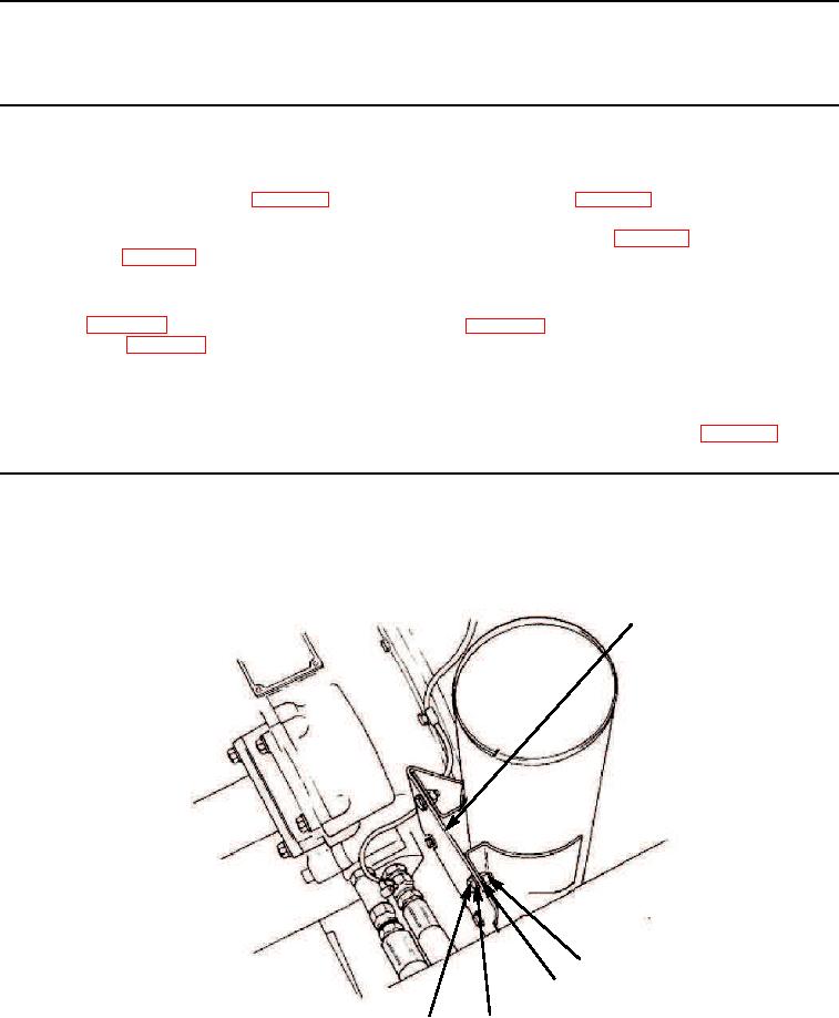
Remove four nuts (Figure 1, Item 2), lockwashers (Figure 1, Item 3), washers (Figure 1, Item 4), and capscrews
(Figure 1, Item 5) from bracket (Figure 1, Item 1). Discard lockwashers.
1
2
3
5
4
M0292105
Figure 1.
Exhaust System Removal.
03/15/2011Rel(1.8)root(maintwp)wpno(M00059)