
9
0
8
2
3
6
1
4
7
5
,
TM 5-3810-305-23
0066
INSTALLATION - Continued
Side Sloping Dash Panel - Continued
NOTE
Install wires as tagged during removal.
2.
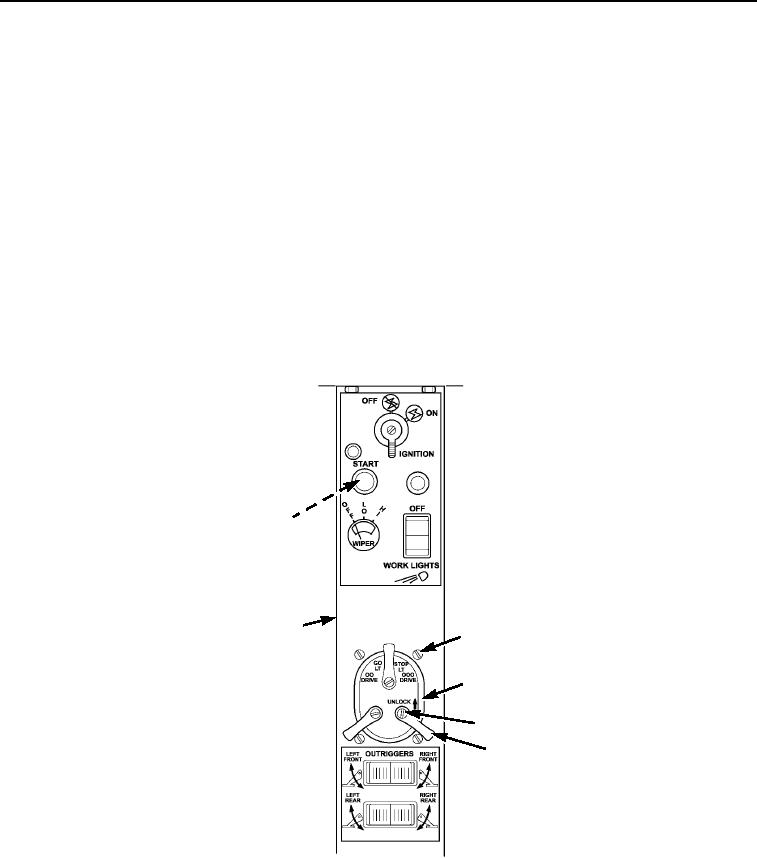
Push start button (Figure 19, Item 7) in through rear of sloping dash panel (Figure 19, Item 6).
3.
Connect wires (Figure 19, Item 8) to back of start button (Figure 19, Item 7).
4.
Screw rubber cover (Figure 19, Item 10) on back of start button (Figure 19, Item 7) and tighten nut
(Figure 19, Item 9).
5.
Connect wires (Figure 19, Item 3) to master light switch (Figure 19, Item 2).
6.
Push master light switch (Figure 19, Item 2) up through panel and install four screws (Figure 19, Item 1).
7.
Install three levers (Figure 19, Item 5) on master light switch (Figure 19, Item 2) and install three screws
(Figure 19, Item 4) in levers.
M0508105
Figure 19. Side Sloping Dash Panel Installation.
03/15/2011Rel(1.8)root(maintwp)wpno(M00072)