
TM 5-3810-305-23
0066
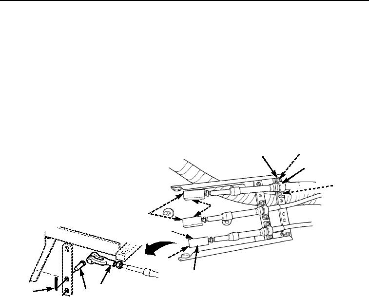
REMOVAL - Continued
Right Console - Continued
9.
Remove six nuts (Figure 14, Item 2), lockwashers (Figure 14, Item 3), and capscrews (Figure 14, Item 1).
Discard lockwashers.
10.
Remove three clamps (Figure 14, Item 4) and shims (Figure 14, Item 5).
NOTE
Tag cable terminals and record holes in shifter to aid in assembly.
11.
Remove three cotter pins (Figure 14, Item 7) and pins (Figure 14, Item 8) from cable terminal
(Figure 14, Item 6). Discard cotter pins.
2,3
1
4
5
8
7
8
7
6
6
7
8
M0513105
Figure 14.
Right Console Removal.
03/15/2011Rel(1.8)root(maintwp)wpno(M00072)