
TM 5-3810-305-23
0070
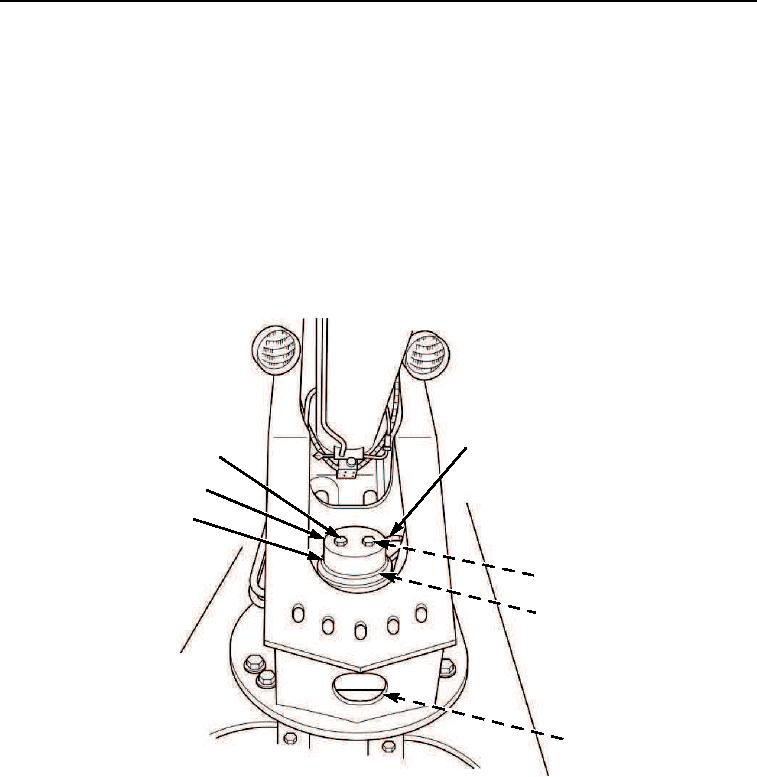
INSTALLATION - Continued
13.
Install cover (Figure 8, Item 7). Make sure upper harness grommet fits in slot on side of cover. Install two
washers (Figure 8, Item 3) and nuts (Figure 8, Item 1).
CAUTION
Secure harness so that it does not drop down around electrical collector ring. Damage to
harness may result.
14.
Connect four knife connectors (Figure 8, Item 2) inside upperstructure. Protect connectors with shrink tubing
or electrical tape. Secure harnesses together with tiedown straps.
15.
Connect four knife connectors (Figure 8, Item 5) to connector ring (Figure 8, Item 6) under carrier near rotary
manifold (Figure 8, Item 4). Protect connectors with shrink tubing or electrical tape. Secure harnesses together
with electrical tiedown straps.
2
1
7
6
3
4
5
M0128105
Figure 8. Electrical Collector Ring Installation.
END OF TASK
03/15/2011Rel(1.8)root(maintwp)wpno(M00076)