
TM 5-3810-305-23
0090
DISASSEMBLY
CAUTION
Care must be taken not to lose two detent springs and balls when handling control valve.
Failure to follow this caution may result in damage to equipment.
NOTE
Record bore location of balls, springs, and rollers to aid installation.
1.
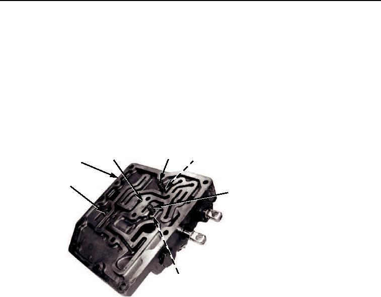
Remove two detent springs (Figure 1, Item 3) and balls (Figure 1, Item 4) from control
valve (Figure 1, Item 1).
2.
Remove rolled needle (Figure 1, Item 5) and roller (Figure 1, Item 2).
3
2
4
1
5
3
4
M0223105
Figure 1. Control Valve Disassembly.
03/15/2011Rel(1.8)root(maintwp)wpno(M00099)