
TM 5-3810-305-23
0090
ASSEMBLY - Continued
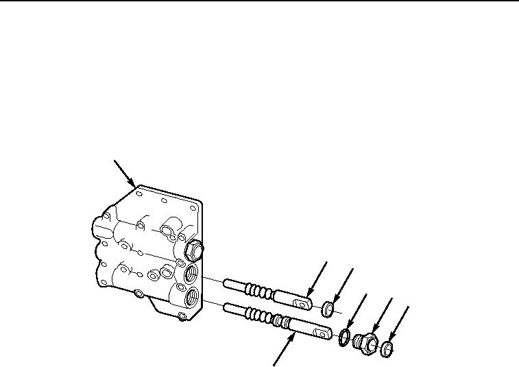
6.
Install new seal (Figure 11, Item 3) in control valve (Figure 11, Item 1).
7.
Install new seal (Figure 11, Item 6) and o-ring (Figure 11, Item 4) on plug (Figure 11, Item 5).
8.
Install forward/reverse stem (Figure 11, Item 2) in control valve (Figure 11, Item 1).
9.
Install stem (Figure 11, Item 7) in control valve (Figure 11, Item 1).
10.
Install plug (Figure 11, Item 5) in control valve (Figure 11, Item 1).
1
2
3
4
5
6
7
M0226105
Figure 11.
Control Valve Assembly.
03/15/2011Rel(1.8)root(maintwp)wpno(M00099)