TM 5-3810-305-23
0090
ASSEMBLY - Continued
17.
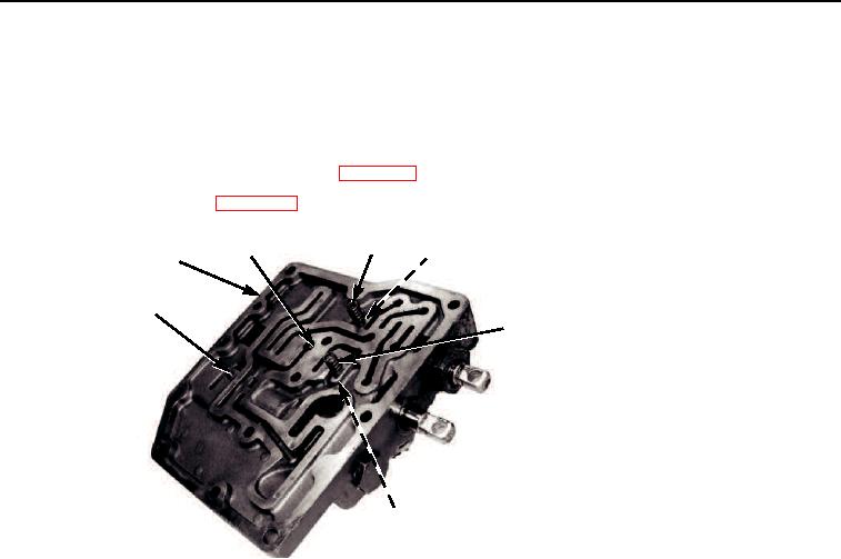
Install two balls (Figure 16, Item 4) and detent springs (Figure 16, Item 3) in back side of control valve
(Figure 16, Item 1).
18.
Ensure rolled needle (Figure 16, Item 5) and roller (Figure 16, Item 2) are properly seated.
19.
Install control valve linkages and hoses (WP 0139).
20.
Connect battery cables (WP 0076).
3
2
4
1
5
3
4
M0223105
Figure 16.
Control Valve Assembly.
END OF TASK
PRESSURE CHECKS
NOTE
Pressure checks must be made with transmission oil temperature at 160F to 190F
(71C to 88C).
Pressure Regulator Test
1.
Install 200 psi (1,379 kPa) gage in port (Figure 17, Item 5).
2.
Position forward-neutral-reverse shift lever in neutral and 1-2-3-4 shift lever in 1.
3.
Start engine and operate at approximately 2,000 rpm while reading pressure indicated on gage.
Pressure must be 155 to 180 psi (1,069 to 1,241 kPa). If pressure is within this range, proceed to Clutch
Pressure Test. If pressure is not within this range, proceed to Step 4.
4.
Shut engine OFF.
5.
Remove plug (Figure 17, Item 4), o-ring (Figure 17, Item 3), regulator spool (Figure 17, Item 2) and shims
(Figure 17, Item 1). Discard o-ring.
6.
Check o-ring for nicks or damage and regulator spool (Figure 17, Item 2) to ensure that it works freely in
valve body.
7.
Add or remove shims (Figure 17, Item 1) to increase or decrease pressure.
03/15/2011Rel(1.8)root(maintwp)wpno(M00099)

