
TM 5-3810-305-23
FIELD MAINTENANCE
FRONT AND REAR DRIVESHAFT MAINTENANCE
INITIAL SETUP:
References
Tools and Special Tools
Tool Kit, General Mechanic's (WP 0171, Table 1,
Item 17)
10 Ton Jack Stand (WP 0171, Table 1, Item 19)
Equipment Condition
Wrench, Torque, Click, Ratcheting 3/8 Inch Drive,
Vehicle parked on level ground (TM
75 ft-lb (WP 0171, Table 1, Item 36)
5-3810-305-10)
Boom in horizontal position and fully retracted (TM
5-3810-305-10)
Materials/Parts
Rag, Wiping (WP 0170, Table 1, Item 52) Qty: 1
REMOVAL
Front Driveshaft
1.
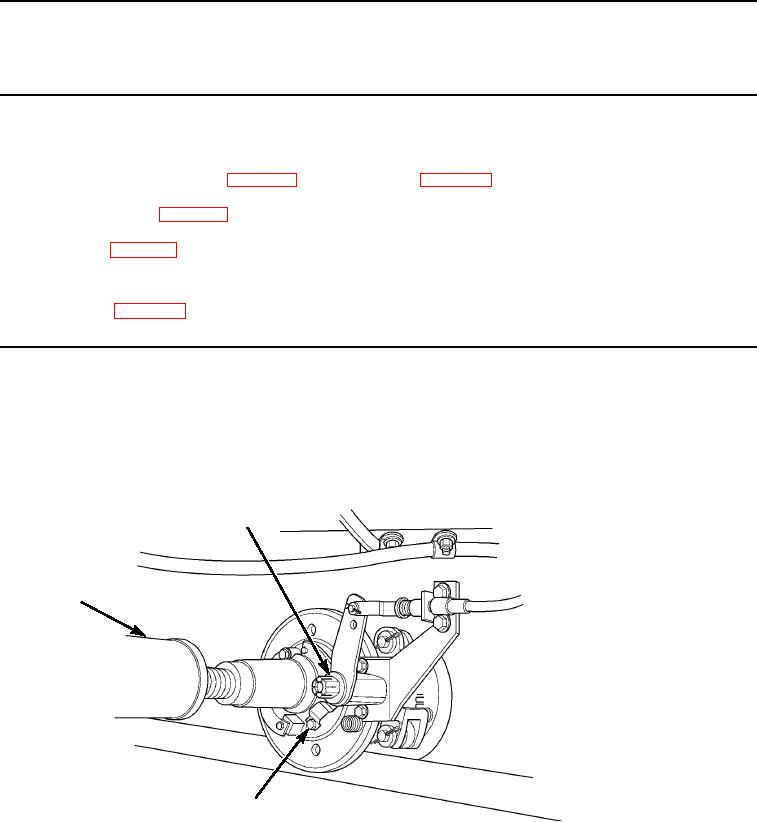
Support front end of driveshaft assembly (Figure 1, Item 1) with jack stand.
2.
Remove four capscrews (Figure 1, Item 3) from front spider bearing assembly (Figure 1, Item 2).
2
1
3
M0187105
Figure 1.
Front Driveshaft Removal.
03/15/2011Rel(1.8)root(maintwp)wpno(M00103)