
TM 5-3810-305-23
0093
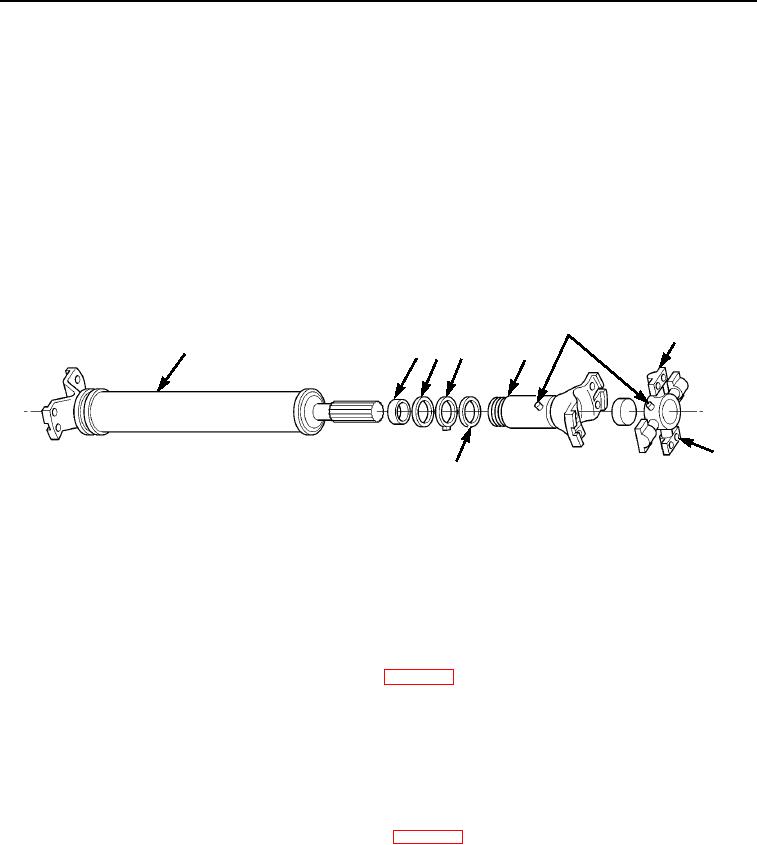
DISASSEMBLY - Continued
Front Driveshaft - Continued
3.
Remove four capscrews (Figure 4, Item 8) and front spider bearing assembly (Figure 4, Item 7) from yoke
assembly (Figure 4, Item 5).
4.
Remove two grease fittings (Figure 4, Item 6) from yoke assembly (Figure 4, Item 5).
5.
Loosen dust cap (Figure 4, Item 2).
6.
Separate slip yoke assembly (Figure 4, Item 5) from tube assembly (Figure 4, Item 1).
7.
Remove washer (Figure 4, Item 3), felt washer (Figure 4, Item 4), and washer (Figure 4, Item 3) from tube
assembly (Figure 4, Item 1).
8.
Remove dust cap (Figure 4, Item 2) from tube assembly (Figure 4, Item 1).
6
7
1
2 3 4
5
8
3
M0190105
Figure 4.
Front Driveshaft Disassembly.
END OF TASK
CLEANING
Front Driveshaft
Clean parts IAW General Maintenance Instructions (WP 0162).
END OF TASK
INSPECTION
Front Driveshaft
Inspect parts IAW General Maintenance Instructions (WP 0162).
END OF TASK
03/15/2011Rel(1.8)root(maintwp)wpno(M00103)