
TM 5-3810-305-23
0105
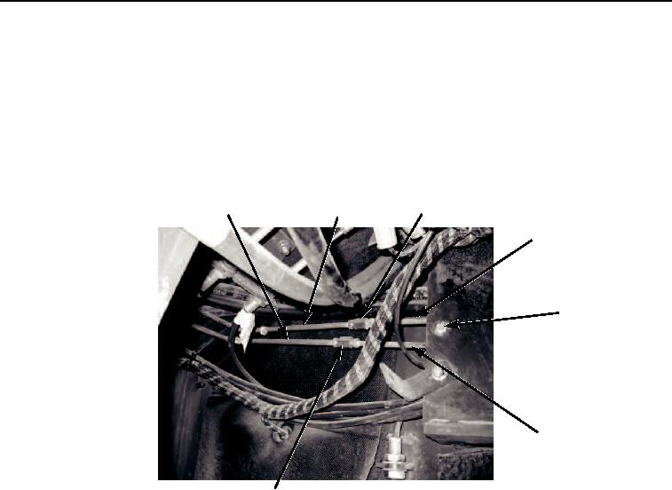
REMOVAL - Continued
5.
Disconnect tube (Figure 2, Items 2 and 4) from coupling (Figure 2, Item 3).
6.
Disconnect tube (Figure 2, Items 1 and 9) from coupling (Figure 2, Item 10).
7.
Remove tube (Figure 2, Items 1 and 2) from vehicle.
8.
Remove capscrew (Figure 2, Item 5), nut (Figure 2, Item 6), washer (Figure 2, Item 7), and clamp
(Figure 2, Item 8).
1
3
2
4
5,6,7,8
9
10
M0327105
Figure 2.
Hydraulic Brake Lines and Fittings Removal.
03/15/2011Rel(1.8)root(maintwp)wpno(M00116)