
TM 5-3810-305-23
0105
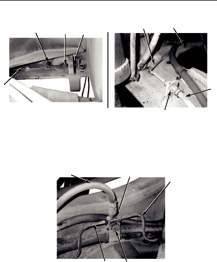
REMOVAL - Continued
7,8,9
6
1,2,3
4
5
6
10
11
M0330105
Figure 5.
Hydraulic Brake Lines and Fittings Removal.
29.
Disconnect hose (Figure 6, Item 1) from tee (Figure 6, Item 2).
30.
Disconnect tubes (Figure 6, Items 3 and 7) from tee (Figure 6, Item 2).
31.
Remove capscrew (Figure 6, Item 6), washer (Figure 6, Item 5), and nut (Figure 6, Item 4).
32.
Remove tee (Figure 6, Item 2) from vehicle.
1
2
3
7
4,5,6
M0331105
Figure 6.
Hydraulic Brake Lines and Fittings Removal.
03/15/2011Rel(1.8)root(maintwp)wpno(M00116)