
TM 5-3810-305-23
0105
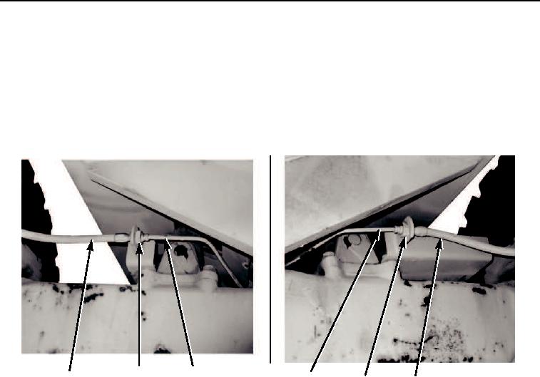
INSTALLATION - Continued
5.
Install right rear tube (Figure 10, Item 4) on vehicle and connect to coupler (Figure 10, Item 5).
6.
Install right rear hose (Figure 10, Item 6) and connect to coupler (Figure 10, Item 5).
7.
Install left rear tube (Figure 10, Item 3) on vehicle and connect to coupler (Figure 10, Item 2).
8.
Install left rear hose (Figure 10, Item 1) and connect to coupler (Figure 10, Item 2).
2
3
1
4
6
5
M0332105
Figure 10. Hydraulic Brake Lines and Fittings Installation.
03/15/2011Rel(1.8)root(maintwp)wpno(M00116)