TM 5-3810-305-23
0106
REMOVAL - Continued
2.
Remove cotter pin (Figure 2, Item 10) and pin (Figure 2, Item 8) from booster valve (Figure 2, Item 9).
Discard cotter pin.
3.
Remove locknut (Figure 2, Item 19), bushing (Figure 2, Item 20), washer (Figure 2, Item 21), and bolt
(Figure 2, Item 3) from bracket (Figure 2, Item 11). Discard locknut.
4.
Remove pedal (Figure 2, Item 2), bushing (Figure 2, Item 1), and rubber pedal (Figure 2, Item 14) as an
assembly from bracket (Figure 2, Item 11).
5.
Remove bushing (Figure 2, Item 1) from pedal (Figure 2, Item 2), if necessary.
6.
Remove rubber pedal (Figure 2, Item 14) from pedal (Figure 2, Item 2).
7.
Remove four capscrews (Figure 2, Item 17) and lockwashers (Figure 2, Item 16) from booster valve
(Figure 2, Item 9). Discard lockwashers.
8.
Remove bracket (Figure 2, Item 12), capscrew (Figure 2, Item 15), nut (Figure 2, Item 13), bumper
(Figure 2, Item 18), and screw (Figure 2, Item 4) from bracket (Figure 2, Item 11) as an assembly.
9.
Remove screw (Figure 2, Item 4), bumper (Figure 2, Item 18), nut (Figure 2, Item 13), and capscrew
(Figure 2, Item 15) from bracket (Figure 2, Item 12).
10.
Remove four nuts (Figure 2, Item 7), lockwashers (Figure 2, Item 6), capscrews (Figure 2, Item 5), and bracket
(Figure 2, Item 11). Discard lockwashers.
1
2
3
4
5
21
20
19
6
18
7
17
8
16
15
9
11 10
12
13
14
M0499105
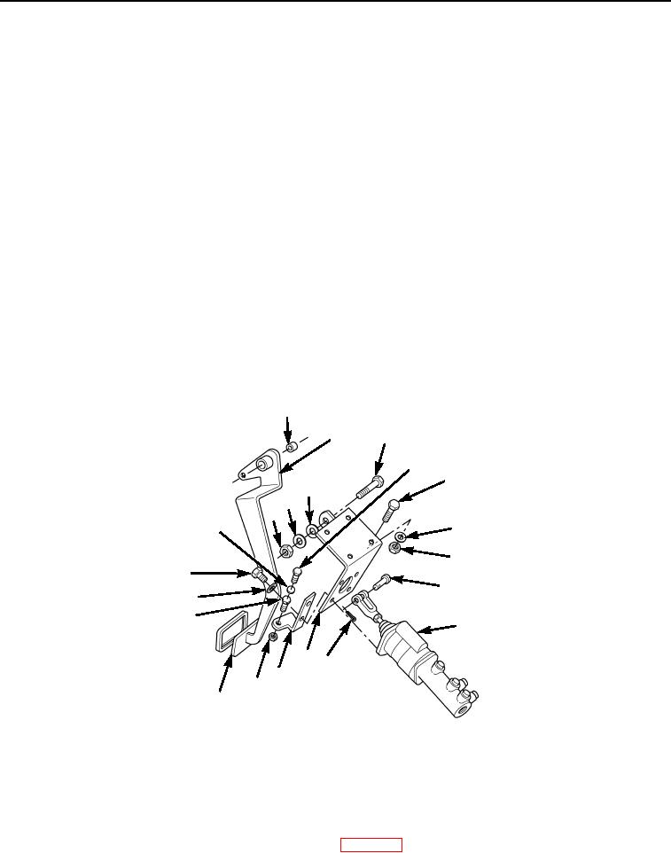
Figure 2.
Brake Pedal and Linkage Removal.
END OF TASK
CLEANING
Clean parts IAW General Maintenance Instructions (WP 0162).
END OF TASK
03/15/2011Rel(1.8)root(maintwp)wpno(M00118)

