
TM 5-3810-305-23
0109
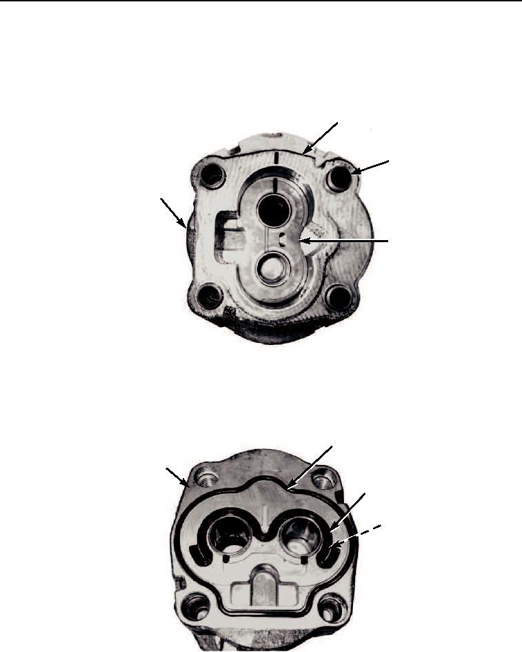
DISASSEMBLY - Continued
7.
Separate gear plate (Figure 6, Item 1) from front flange plate (Figure 6, Item 4).
8.
Remove thrust plate (Figure 6, Item 3).
9.
Remove eight dowel pins (Figure 6, Item 2) from gear plate (Figure 6, Item 1).
1
2
4
3
M0442105
Figure 6. Ground Driven Steering Pump Disassembly.
10.
Remove o-ring (Figure 7, Item 2), back-up ring (Figure 7, Item 4), and o-ring (Figure 7, Item 3) from front flange
plate (Figure 7, Item 1). Discard o-rings and back-up ring.
2
1
3
4
M0443105
Figure 7. Ground Driven Steering Pump Disassembly.
03/15/2011Rel(1.8)root(maintwp)wpno(M00122)