
TM 5-3810-305-23
0117
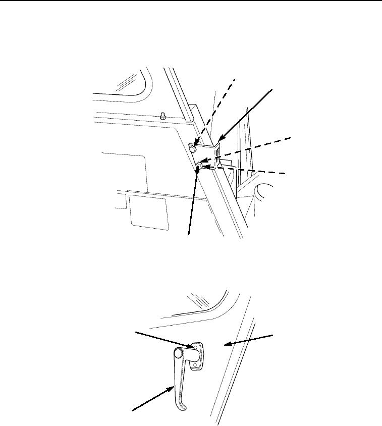
INSTALLATION - Continued
5.
Install spacer plate (Figure 9, Item 1), striker (Figure 9, Item 2), two washers (Figure 9, Item 3), new lockwashers
(Figure 9, Item 4), and capscrews (Figure 9, Item 5) on cab.
1
2
3
4
5
M0577105
Figure 9.
Cab Door Installation.
6.
Install outside handle (Figure 10, Item 3) and two screws (Figure 10, Item 1) on door (Figure 10, Item 2).
1
2
3
M0576105
Figure 10. Cab Door Installation.
03/15/2011Rel(1.8)root(maintwp)wpno(M00130)