
TM 5-3810-305-23
0125
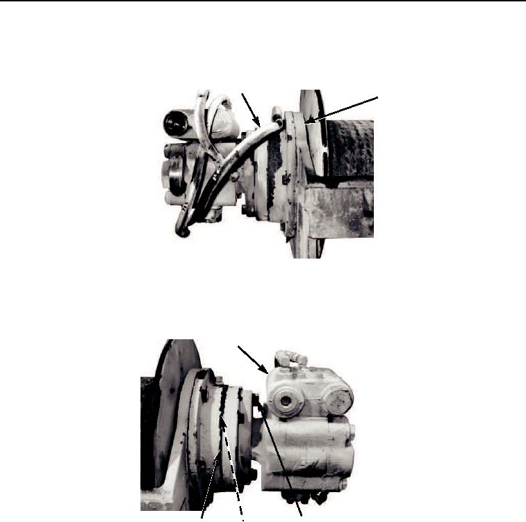
DISASSEMBLY - Continued
5.
Disconnect hydraulic hose (Figure 3, Item 1) from winch (Figure 3, Item 2).
1
2
M0650105
Figure 3. Hydraulic Hose Disassembly.
6.
Remove two capscrews (Figure 4, Item 2), lockwashers (Figure 4, Item 3), motor (Figure 4, Item 1), and o-ring
(Figure 4, Item 4) from motor support (Figure 4, Item 5). Discard o-ring and lockwashers.
1
2,3
5
4
M0651105
Figure 4. Motor Disassembly.
CAUTION
Avoid damaging sealing or bearing surfaces while removing brake cylinder assembly.
Failure to follow this caution may result in damage to equipment.
7.
Remove brake clutch assembly (Figure 5, Item 1) from motor support.
8.
Remove six capscrews (Figure 5, Item 2) and lockwashers (Figure 5, Item 3), and brake cylinder assembly
(Figure 5, Item 5) from winch (Figure 5, Item 4). Discard lockwashers.
03/15/2011Rel(1.8)root(maintwp)wpno(M00141)