
TM 5-3810-305-23
0126
DISASSEMBLY - Continued
17.
Remove four dowel pins (Figure 11, Item 1) from port end cover (Figure 11, Item 2), if inspection
proves necessary.
2
1
M0633105
Figure 11.
Winch Motor Disassembly.
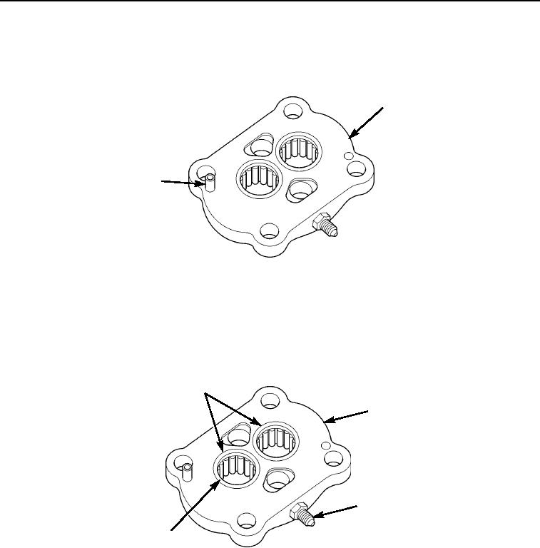
18.
Remove two bearings (Figure 12, Item 1) and ring seal (Figure 12, Item 4) from port end
cover (Figure 12, Item 2).
19.
Remove adapter with o-ring (Figure 12, Item 3) from port end cover (Figure 12, Item 2). Discard adapter with
o-ring.
1
2
3
4
M0634105
Figure 12.
Winch Motor Disassembly.
03/15/2011Rel(1.8)root(maintwp)wpno(M00143)