TM 5-3810-305-23
0132
ASSEMBLY
1.
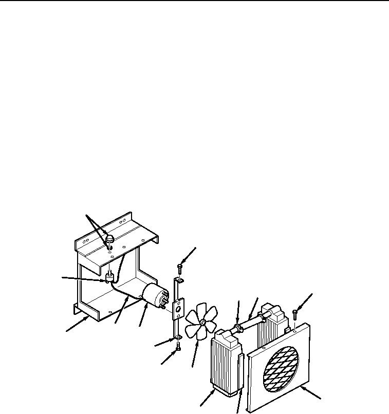
Install switch assembly (Figure 10, Item 13) in casing assembly (Figure 10, Item 12) and secure with nut.
Install knob (Figure 10, Item 1) on switch assembly.
2.
Install motor (Figure 10, Item 10) and two nuts on motor support (Figure 10, Item 9).
3.
Install motor (Figure 10, Item 10) and motor support (Figure 10, Item 9) as an assembly to casing
(Figure 10, Item 12).
4.
Install two screws (Figure 10, Item 2) on motor support (Figure 10, Item 9).
5.
Connect wire assembly (Figure 10, Item 11).
6.
Install fan (Figure 10, Item 8) and align setscrew with flat side of motor support
(Figure 10, Item 9). Tighten setscrew.
7.
Install hose (Figure 10, Item 4) and two clamps (Figure 10, Item 3) to two heater cores (Figure 10, Item 7).
8.
Install two pads (Figure 10, Item 6) on heater cores (Figure 10, Item 7).
9.
Install hose (Figure 10, Item 4), pads (Figure 10, Item 6), clamps (Figure 10, Item 3), and two heater cores
(Figure 10, Item 7) as an assembly.
1
2
13
2
4
3
11
10
12
9
2
8
5
7
6
M0525105
Figure 10.
Heater Assembly.
03/15/2011Rel(1.8)root(maintwp)wpno(M00148)

