
Manifold Gauge Set Installation
1. Purging Air From Gauge Set Hoses
Environmental regulations require that all service hoses have a shutoff
valve within 12 inches of the service end. These valves are required to
ensure only a minimal amount of refrigerant is lost to the atmosphere. R-
12 gauge set hoses have a valve near the end of all three hoses. R-134a
gauge sets have a combination quick disconnect and shutoff valve on the
high and low sides. The utility (center) hose also requires a valve.
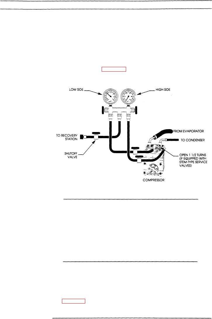
The initial purging is best accomplished when connected to recovery or
recycle equipment. Figure 8-3 illustrates the gauge set connections for
purging and refrigeration recovery.
The purging setup for mani-
fold gauge set and compres-
sor service valves are shown
here.
Note:
The manifold gauges read system pressure when the
hand valves are closed if the hose end valves, and the
stem type service valves (if included) are open.
2. Adding Refrigerant to the System
Now that the gauges are connected, you may need to add some refrigerant
to the AC system before you can do an effective performance inspection.
However, if leaks are obvious they should be repaired prior to adding
refrigerant.
Note:
Loss of some refrigerant is not unusual over an ex-
tended period of time. Adding refrigerant is a typical
procedure when the AC system is maintained on a regu-
lar basis.
When adding refrigerant to the system, connect the center hose from the
manifold gauge set to the refrigerant dispensing valve on the container.
Figure 8-4 illustrates this connection.
8-7