
TM 5-3810-307-24-1-2
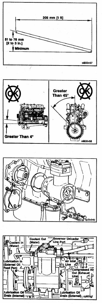
The oil drain system is gravity based, and therefore, re-
quires installation of the drain line to be free of low spots
or traps with a downward flow of 51 to 76 mm [2 to 3
inches] per 305 mm [1 foot] minimum fall.
The drain line must enter the engine at the point above
the engine oil level to prevent a back flow restriction.
Where flange mount compressor drainage is internal to
the compressor with engine oil drain or return through
engine block holes, vehicle installation tilt angles greater
than 4 degrees from the horizontal or roll angles
exceeding 45 degrees from the vertical position, can
cause less than optimum drain back conditions.
When mounting air compressors to the engine always
use new Original Equipment Manufacturer (OEM) sup-
plied gaskets to provide a leak free connection. Do not
use form-in place or similar sealant materials as oil drain
holes can become blocked.
Cooling System
The engine cooling system provides the cooling water for
air compressors. The air compressor function produces
high temperature exhaust air, which if not con-trolled,
causes excessive carbon formation in the com-pressor
head and discharge or exhaust line. It can shorten
compressor life.
The following cooling system installation guidelines will
provide optimum compressor performance.