
TM 5-3810-307-24-1-2
Impact Hammer - Lubrication System Operation (Refer To Figure K-9.)
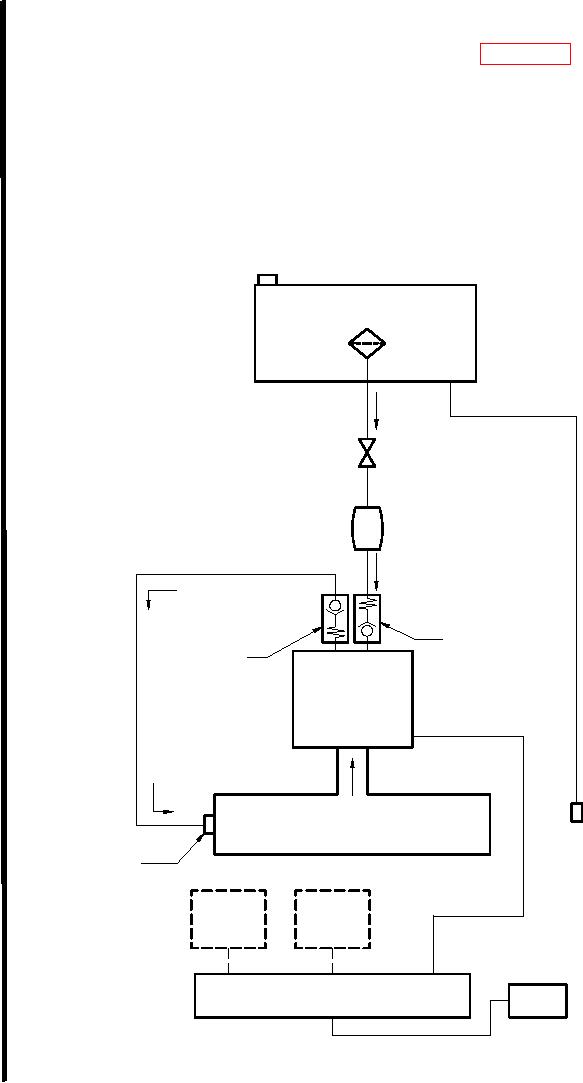
The lubricating system delivers lubricating oil to the lower cylinder and is controlled by the air pressure
in the lower cylinder.
Lubricating oil is supplied to the oil pump by gravity flow from the lubricating oil tank. It is then pumped
by the oil pump to a fitting on the lower cylinder.
Operation of the oil pump is similar to the fuel pump operation. The plunger in the oil pump is operated
by the change in air pressure in the lower cylinder during operation, forcing lubricating oil through the
outlet check valve and into the lower cylinder via the lubrication fitting.
An indicator on the oil pump will pop in and out as the piston falls to indicate proper operation of the oil
pump.
Oil Tank Plug / Vent Valve
Lubricating
Suction
Oil Tank
Strainer
Assembly
Oil Pump
Feed
Shutoff Valve
Oil Pump
Inline
Priming Pump
Inlet
Check Valve
Outlet
Check Valve
Oil Pump
Oil Tank
Fill Line and
Quick Connect
Fitting
Air Pressure
(Labeled "OIL")
Lubrication
Fitting
Lower Cylinder
Fuel
Fuel
Injector
Injector
Waste Fuel Drip Tank
Quick Connect Fitting
Figure K-9. Lubrication System Schematic
K-24 Change-1