
CHECK EXHAUST VALVE CLEARANCE
stem and
the valve bridge adjustment
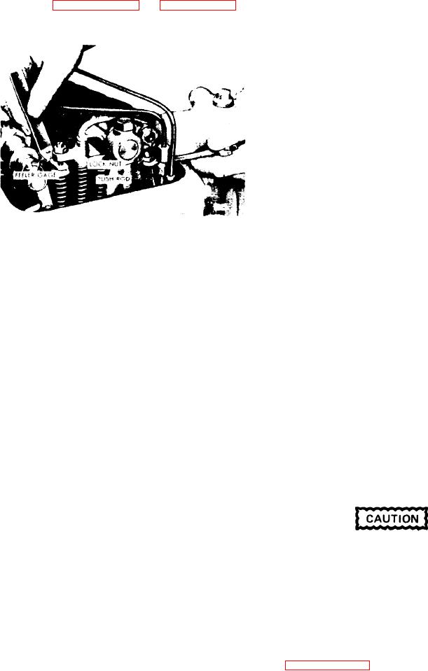
ADJUSTMENT
screw (see
Adjust the
push rod to obtain a smooth
1. With the engine operating 100oF
pull on the
feeler gauge.
(38C) or less, check the valve
clearance.
2 . If a 0.016" feeler gage (J 9708-01)
0.004" will pass between the valve stem
and the rocker arm bridge, the valve
clearance is satisfactory. If necessary
adjust the push rod.
FUEL INJECTOR TIMING
General
To time an injector properly, the injector
follower must be adjusted to a definite
Figure 11H-1. Adjusting Valve
height relation to the injector body.
Clearance
All of the injectors can be timed in firing
order sequence during one full revo-
6. Remove the feeler gage,
Hold the
lution of the crankshaft. Refer to Gen-
push rod with a 5/16" wrench and tight-
en the lock nut with a 1/2" wrench.
eral Specifications in Subsection 11A for
the engine firing order.
7. Recheck the clearance. At this time if
the adjust is correct, the 0.015" gage
will pass freely between the valve stem
T i m e Fuel Injector
and the adjustment screw. The 0.017"
After the exhaust valve clearance has
will not pass through, Readjust the push
been adjusted, time the fuel injectors as
rod, if necessary.
follows:
8. Adjust and check the remaining ex-
haust valves in the same manner as
1. Place the governor speed control lever
above.
in the idle speed position. If a stop le-
ver is provided, secure it in the stop
position.
VALVE CLEARANCE ADJUSTMENT (HOT
ENGINE).
Maintaining
normal
engine
op-
2. Rotate the crankshaft, manually or
erating temperature is particularly im-
with the starting motor, until the ex-
portant when making the final exhaust
valve clearance adjustment. If the en-
haust valves are fully depressed on the
gine is allowed to cool before setting any
particular cylinder to be timed.
of the valves, the clearance when run-
ning
at
full
load,
may
become
insufficient.
I f a wrench is used on the crank-
1. With the engine at normal operating
temperature (refer to Subsection 11A),
shaft bolt at the front of the en-
recheck the exhaust valve clearance with
gine, do not turn the crankshaft
i n a left-hand direction of rotation
feeler gage J 9708-01. At this time, if
or the bolt may be loosened.
the valve clearance is correct, the 0.013"
gage will pass freely between the valve
stem and the valve bridge adjusting
3. Place the small end of the injector tim-
screw. The 0.015" feeler gage will not
ing gage in the hole provided in the top
pass through. Readjust the push rod if
of the injector body with the flat of the
necessary.
gage toward the injector follower. Refer
to Figure 11H-2 on page 11H-4.
2. After the exhaust valve clearance has
been adjusted, check the fuel injector
timing.
Engine Tune-Up

