from trip lever over idler sheave on shipper shaft,
(3) Install
remaining
teeth
in
a
similar
manner.
through equalizer sheave on equalizer bracket back to
take up drum on shipper shaft (fig. 4-7). The revolving
frame trip line runs from equalizer bracket on boom,
through guide sheaves on bracket mounted on revolving
frame at boom foot to bellcrank lever mounted
underneath revolving frame. When properly adjusted
lever (fig. 2-23) is actuated.
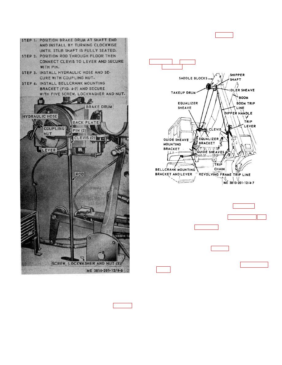
Figure 4-7. Dipper trip lines, installed view.
b. Installation.
(1) Install dipper trip lever (fig. 2-23) and
secure with pin to mounting bracket. Install hydraulic
compensator and line to main header (para's 3-118, 119
and 120).
(2) Refer to figure 4-6 and install dipper trip
mechanism.
(3) Install bellcrank mounting bracket under
revolving frame, and guide sheave mounting bracket on
revolving frame at boom foot (fig. 4-7).
(4) When shovel front end attachment is
installed, install revolving frame trip line.
(5) Adjust dipper trip mechanism (para's 3-37
and 3-38).
Figure 4-6. Dipper trip mechanism, removal
Note. The above procedure assumes that
or installation.
shovel tripping mechanism is installed on boom of
shovel front end attachment.
4-8. Dipper Trip Mechanism and Trip Lines
c. Removal. The entire dipper trip mechanism
may be removed by reversing procedure in b above, or
is used for opening the door of shovel dipper only, but
individual components may be removed for replacement
once installed on main hoist drum shaft, need not be
or repair as follows:
removed when shovel is converted to any other front
(1) Dipper trip clutch mechanism removal.
end arrangement. The boom trip line, consisting of
chain from bucket door latch to dipper handle trip lever;
trip
line
4-7


