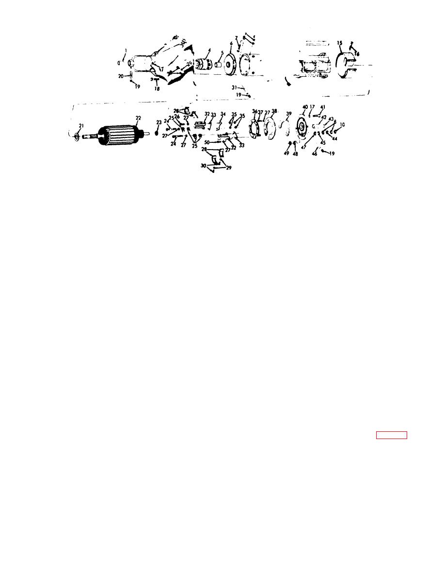
EMC 5-3810-206-35/3
1
Bushing
26
Screw (8 rqr)
2
Drive housing
27
Lockwasher (14 rqr)
8
Thrust washer
28
Brush (8 rqr)
4
Electric engine drive
29
Lockwasher (8 rqr)
5
Bearing
30
Screw (8 rqr)
6
Plate
31
Wick
7
Stud terminal (2 rqr)
32
Brush holder (8 rqr)
8
Fiber washer (8 rqr)
33
Insulator (8 rqr)
9
Lockwasher (4 rqr)
34
Shim (spacer) (2 rqr)
10
Nut (8 rqr)
35
Insulator, fiber (8 rqr)
11
Screw (8 rqr)
36
Brush holder plate
12
Housing
37
Screw (3 rqr)
13
Field coil (2 rqr)
38
Brush holder ring
14
Pole shoe (4 rqr
39
Brush holder plate
1s
Cover band
40
Commutator end bell
16
Screw (2 rqr)
41
Screw (4 rqr)
17
Lockwasher (10 rqr)
42
Bearing
18
Screw (6 rqr)
43
Pipe plug
19
Pipe plug (3 rqr)
44
Nut (2 rqr)
20
Wick
45
Flatwasher
21
Spacer (2 rqr)
46
Wick
22
Armature
47
Flatwasher (2 rqr)
23
Nonmetallic washer
48
Insulator bushing
24
Screw (4 rqr)
49
Insulator bushing (2 rqr)
25
Spring (8 rqr)
50
Screw (8 rqr)
Figure 3-3. Starter motor, exploded view (for engine model 687C-18-ES)
d. Reassembly (Starter Used on Engine Model
(32) insulator (33) and shim (34) from brush
687C-18-ES).
holder (36).
(13) Slide armature (22) out of field frame and
remove non-metallic washer (23) and spacer (21).
(1) Apply a light coating of lubricating oil to
(14) Remove three screws (37), lockwashers
drive shaft of the armature.
(27), brush holder ring (88), and brush holder plate (39)
(2) Position terminal stud (7, fig. 3-3) in
from end bell (40).
housing (12), and secure with washer (8), lockwasher
(15) Remove eight screws (11) and remove
(9), and nut (10).
four pole shoes (14), field coil (13), and field coil leads
(3) Position field coils (13) in housing (12) and
from housing (12).
secure with pole shoes (14) and screws (11).
(16) Remove nut (10), terminal stud (7), and
(4) Solder field coil leads to terminal studs (7).
lockwasher (9) from housing (12).
(5) Position brush holder plate (89) and brush
holder ring (38) on commutator end bell (40) and secure
c. Cleaning, Inspection, Testing, and Repair. Refer
with three lockwashers (27) and screws (87).
to TM 5-764 for instructions on cleaning, inspection,
testing and repair of electric motors.
AGO 20051A
3-6


