(8) Remove sleeve berings (52) from carbody.
b. Cleaning , Inspection and Repair.
(1) Clean all parts thoroughly.
(2) Inspect crawler frame and propelling gear oil pan
for cracks, breaks, or other damage Inspect swing gear,
steering gear, bearing caps, and bearings for damage or
excessive wear. Inspect mounting hardware for burs or
stripped threads. Inspect lubrication lines (copper tubes)
for breaks or leaks. Inspect wear plante for excessive
wear.
(3) Repair by straightening bends, welding cracks or
breaks, or replacing defective components or mounting
hardware
c. Reassembly and Installation
(1)
Install bearings (562) in carbody.
(2)
Install copper tubes (18, 15, and 18, fig.
(3)
Install track support rollers (para 5-10).
(4)
Install crawler idler shaft and sprockets
(5)
Install pipe spacers (20), bolts (19),
lockwashers (86), and nuts (88).
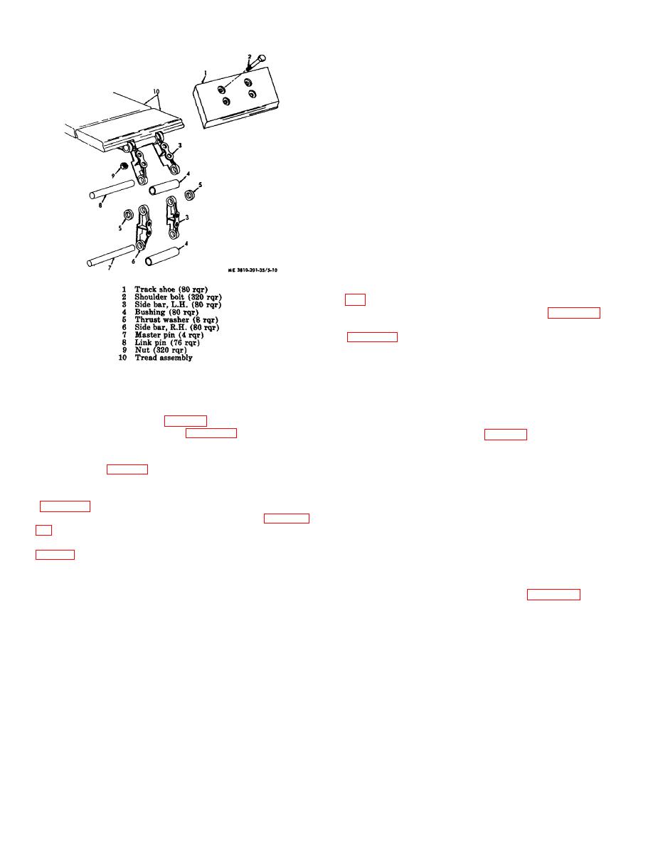
Figure 5-10. Crawler track, disassembly and reassembly
(6)
Lift swing gear carefully into place on top
of frame
NOTE
(7)
Install sleeve nuts (9),bolts (55 and 56),
lockwashers (10), and nuts (11).
To remove swing gear (8, fig. 5-6), the revolving frame
(8)
Install horizontal propelling shaft (para 5-
must be removed from crawler (para 2-10).
18). Be sure shims (88, 84, fig. 5-6) are assembled in
same position as removed, then install bearing cape (21,
(3)
Remove nuts (11), lockwashers (10),
85, and 89).
sleeve nuts (9, fig. 5-6), and bolts (56 and 56), then lift
(9)
Install bolts (82), lockwashers (40), and
off swing gear (8).
nuts (41).
(4)
Remove crawler idler shaft and sprocket
(10)
Install propelling gear oil pan, propel
chain, and upper track support rollers (TM 5-3810-201-
(5)
Remove track support rollers (para 5-
12).
(6)
Remove copper tubes (k3, 15, and 18,
NOTE
Install wearing plates (53) if they were
(7)
Wearing plates (58) are provided on
removed.
carbody to protect against wear by the propelling chains
When wear plates are worn, cut them off with a welding
(11)
Install revolving frame (para 2-10).
torch and weld on new wear plates
(12)
Lubricate (LO 5-3810-201-12).
AGO 20051A
5-12


