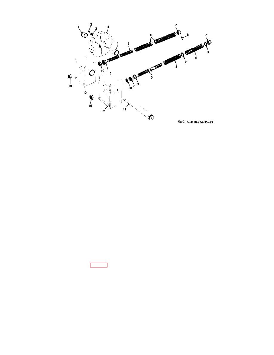
1
Bearing (4 rqr)
7
Nut ( rqr)
2
Fitting (2 rqr)
8
Cotterpin (8 rqr)
3
Bushing (2 rqr)
9
Flatwasher (12 rqr)
4
Idler sprocket (2 rqr)
10
Nut (8 rqr)
5
Adjusting rod (4 rqr)
11
Idler shaft (2 rqr)
6
Spring (8 rqr)
12
Adjusting block (4 rqr)
Figure 5-7. Crawler idler sprocket and idler shaft, exploded view.
(3) Remove nuts (38), lockwashers (86), bolts
(5) Remove two bearings (1) from idler
(48), bearing caps (45), rollers (46) and roller shafts from
sprocket (4), then remove fitting (2) from bush-ing (3),
side frame.
and bushing (3) from idler sprocket.
(4) Install by reversing procedures in steps (1)
(6) Remove four cotterpins (8) from nuts (7)
through (3) above.
(7) Remove nuts (10 and 7) from front of
adjusting rod (5), then remove fiat washer (9).
b. Cleaning, Inspection, and Repair.
(8) Remove nut (7) and flatwasher (9) from
rear of adjusting rod (5).
(1) Clean all parts and dry thoroughly.
(9) Remove adjusting rod (5) and springs (6)
(2) Inspect all track support rollers for
from crawler frame.
excessive wear or an out-of-round condition. Inspect all
(10) Repeat steps (6) through (9) above for
bearings and shafts for scoring or excessive wear.
remaining adjusting rod.
(3) Repair by replacing all defective parts.
(11) Install by reversing procedures in steps (1)
through (10) above, then adjust tracks (TM 5-3810-201-
5-11.
Crawler Idler Sprocket and Idler Shaft
12).
a. Removal and Installation.
b. Cleaning, Inspection, and Repair.
(1) Remove crawler track (TM 5-3810-201-
(1) Clean all parts and dry thoroughly.
12).
(2) Inspect adjusting blocks, idler shaft, idler
(2) Remove two nuts (10, fig. 5-7) from front
sprocket, or flatwashers for wear or other defect. Inspect
of adjusting blocks (12), then remove idler sprocket (4),
springs for damage or weakness. Inspect adjusting rod,
adjusting blocks (12), and shaft (11) from crawler frame.
and nuts for defective threads. Inspect bearings, for
(3) Pull two adjusting blocks (12) from shaft
wear, or scoring. Inspect fittings to assure grease run
(11).
through.
(4) Slide idler sprocket (4) from shaft (11).
5-8


