engine (para 2-11) for an investigation of cause(s).
k. Hot Engine Indicator (Warning) Light. This light
system is defective, and that The should stop engine
l. Engine Oil Pressure Indicator. This indicator
in lubrication system. The pressure indication at idle
speed should be 15 psi or above. Normal operating
pressure at governed speed is 35 psi.
m. Engine Water Temperature Indicator.
This
indicator (fig. 2-22), when engine is operating, indicates
temperature of coolant. Normal operating temperature
should range between 160 and 180 . If operating
F
F
temperature is not reached in a reasonably short time,
stop engine (para -1 1) and determine cause(s).
n. Ammeter. The ammeter (9g. 2-22), while
engine is operating, gives reading of battery condition.
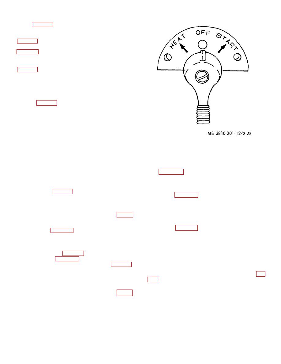
Figure 2-25. Heat-start switch.
When pointer is at zero (dial center) battery is fully
a two position toggle switch that controls all four
charged and generator (alternator) is supplying required
instrument lights for ON-OFF function.
current for operation. Rate of battery discharge (current
use) is indicated by distance pointer is left of zero. Rate
t. Cab Light Switch. Located on lighting control
of charge (after starting) will be indicated by distance
box (fig. 2-24), this two position toggle switch turns
pointer is to right of zero.
interior cab lights ON and OFF.
o. Indicator Fuel Level. Located on operators
u. Upper Floodlight Switch. Located on lighting
instrument panel (fig. 2-22), it indicates quantity of fuel
control box (fig. 2-24) this two position toggle switch
in tank.
turns the duel floodlights ON and OFF. Floodlights are
mounted on top front of cab, and act as headlights when
p. Pressure Primer Discharge (Ether Injector).
crane is traveling.
Located on left side panel behind steering wheel (fig. 2-
24), the ether injector forces ether vapor into air intake
v. Lower Floodlight Switch. Located on lighting
manifold while trigger is held down, as an aid to starting
control box (fig. 2-24) this two position toggle switch
in cold weather (para 2-25). Release pressure on trigger
turns single floodlights, mounted on either side of boom
to stop ether vapor entry (after engine is running).
foot, ON and OFF.
q. Heat-Start Switch (On Models With DS3STA
w. Heater Control Valve. These two valves (fig.
226) located on left side of engine, controls flow of
weather starting (para 2-25) for the model D333TA
heated coolant from engine to personnel heater.
engine, and will replace starter push switch (fig. 2-22)
on operator's instrument panel as D333TA engines are
installed.
Refer to paragraph 225 for operating
instructions.
controls opening of dipper door when operating with
shovel front end attachment. Pull this lever toward
operator to open dipper door. Release lever the instant
24) must be installed when swing lock is disengaged
dipper door opens.
(para ab below), to prevent swing lock from engaging
while crane-shovel is in operation.
y. Engine Throttle Control Lever. Located on left
compartment panel at rear of operator's seat
s. Instrument Panel Light Switch. This switch (fig.
2-24), mounted on lighting control box, is
2-25


