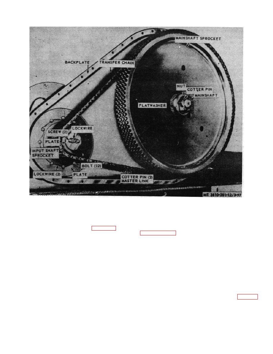
Figure 3-84. Transfer chain, removal and installation
3-108. Main Shaft Sprocket
(3) Remove cotterpin, nut, and flatwashers
from mainshaft, then remove mainshaft sprocket.
a. Removal and Installation.
(4) Install in reverse order.
(1) Remove transfer chain case cover (para 3-
105).
b. Cleaning, Inspection and Repair. Clean, inspect,
and repair in manner similar to that described in
(2) Remove transfer 'chain (para 3-106).
paragraph 3-107, above.
Section XVII. HYDRAULIC SYSTEM
When pressure is released from pedal or lever, springs
3-109. General
cause pistons in hydraulic cylinders to return to normal
position.
a. Description. Each hydraulic control lever or foot
pedal is connected to a master cylinder (compensator).
Each master cylinder is connected by a hydraulic line to
present in the hydraulic system, controls become
an hydraulic cylinder. The hydraulic cylinder is connected
"spongy" and do not hold brake or clutch firmly as they
to brake, clutch, or other mechanism by mechanical
should. To remove air from system proceed as follows:
linkage. When the lever or foot pedal is moved, there is a
(1) Fill hydraulic tank with clean hydraulic fluid (para 3-18
corresponding movement of the piston in master cylinder,
and LO 5-3810-206-12). Check level in tank frequently
which transmits fluid to hydraulic cylinders, thus actuating
during bleeding operation, to prevent air from entering
brake or clutch.
supply line.
3-91


