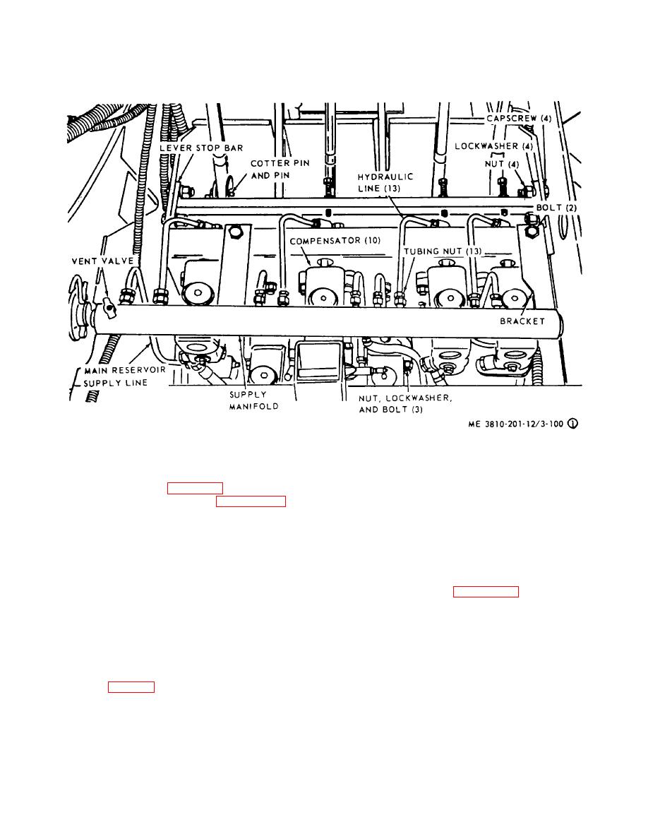
NOTE:
TAG, DISCONNECT, AND PLUG ALL HYDRAULIC LINES REMOVED, THEN PLUG OR
COVER PORTS OF COMPENSATORS TO PREVENT CONTAMINATION OF HYDRAULIC
SYSTEM.
Figure 3-87. Lever stand, showing compensator, lever, pedal and linkage removal and adjustment points (sheet
1 of 2).
(cylinder) from lever stand (para 3-112).
(3) Minor adjustment of foot pedals are made
(3) Refer to sheet 2 of figure 3-87 and
by connecting links to pedals in either the front or rear
remove boom hoist lever and linkage from lever stand.
holes in lower portion of pedal. Pus rod adjustment at
pedal compensator are made in a manner similar to that
(4) Install in reverse order.
described in (2) above.
c. Cleaning, Inspection and Repair.
(1) Clean all parts in an approved cleaning
3-114. Swing and Propel Shiner Lever and Linkage
solvent and dry thoroughly.
a. Removal and Installation
(2) Visually inspect all parts for breaks,
(1) Refer to figure 3-88 and remove swing
cracks, deformation, or excessive wear.
Inspect
and propel shifter lever and linkage.
mounting hardware for burs, or stripped threads.
(2) Install in reverse order.
(3) Repair by replacing defective parts or
b. Cleaning, Inspection, and Repair.
mounting hardware.
(1) Clean all parts in an approved cleaning
d. Adjustment.
solvent and dry thoroughly.
(1) Make adjustment to mechanical linkage
(2) Visually inspect all parts for excessive
by lengthening or shortening adjusting setscrews in lever
wear, bends, breaks, or other defect. Inspect mounting
bar (sheet 2 of fig. 3-87) or clevis at rod end.
hardware for burs or stripped threads.
(2) Adjust the adjusting screws at both
(3) Repair by replacing damaged parts or
compensator push rods until lever remains in neutral
defective hardware.
when push rods are snug against piston.
c. Adjustment. Adjust the linkage for positive
3-94


