TM 5-3810-206-35
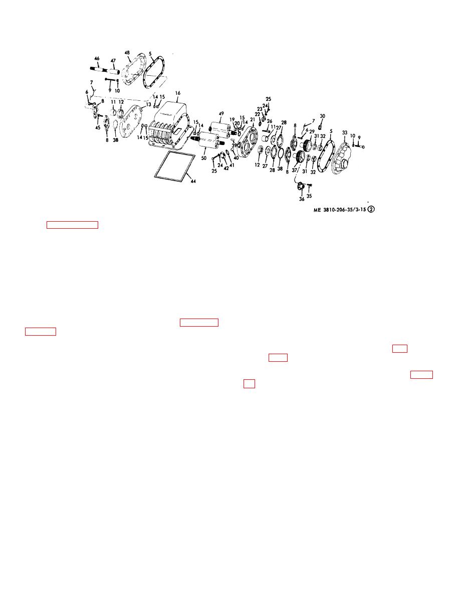
KEY to fig. 3-15 (sheet 2 of 2):
46 Shaft
47 Coupling (2 rqr)
48 Cover
49 Driven rotor
50 Drive rotor
Rear blower
Figure 3-15. Blowers, exploded view (sheet 2 of 2).
(6) Remove eight capscrews (45) from end
(15) Remove eight capscrews (26) from end
plate (13) and lift end plate from rotor shaft and blower
plate (21) then slide end plate (21) from rotor shafts.
housing (16).
Remove seals (19) and shims (20).
(7) Remove seal rings (14) and seal (15) from
(16) Remove seal rings (14) and seals (15) from
dowels (39).
dowels (39), then slide rotors (18 and 43) from housing
(8) Remove ring (34) and shaft (46, sheet 2 of
(16).
15).
Note.
When disassembling rear
(9) Remove 12 capscrews (9) and lockwashers
blower, rotors (49 and 50, sheet 2, fig.
(10) from gear cover (33) then lift cover (33) and gasket
(5) off rotor shaft (18).
(10) Use a piece of copper or brass rod wedged
(17) Remove capscrews (25, sheet 1 of fig. 3-
between gears (29 and 37) while loosening locknuts
(32).
and 41), and tube nut (40) from end plate (21).
(11) Use a small screwdriver and raise
(18) Reassemble the blowers by reversing the
lockwasher (31) free of slot in locknut (32), then remove
procedures outlined in steps (1) through (17) above.
the locknuts, lockwashers, gears (29 and 37), and shims
d. Cleaning, Inspection, and Repair.
(30) from rotor shaft.
(12) Remove three capscrews (35) and drive
Caution: Discard all washers (1), non-
gear coupling (36) from drive gear (37).
metallic washers (2), shims (3),
(13) Remove two lockwires (7), capscrews (6)
gaskets (5), seals (12), seal rings (14),
and bearing cages (8) from end plate (21).
seals (15), seals (19), shims (20),
(14) Remove seal (38) from bearing cages (8)
gaskets (22), thrustwashers (27),
and slide shims (28), thrustwashers (27), spacers (11),
rotor lockwashers (31), seals (38),
and seals (12) from rotor shafts.
gaskets (41), and gaskets (44) at
every disassembly, and replace with
new items from repair parts kit.
3-18


