TM 5-3810-206-35
(1) Clean all parts and dry thoroughly.
(2) Inspect all parts for damage or defect,
paying particular attention to the following features:
(a) Inspect ring bores in end plates for
excessive wear or roughness. These defects in end
plates will prevent rings from sealing therefore defective
end plates must be replaced.
(b) Inspect bores in each of the bearing
cages.
If bores dimension exceeds 1.3765 inches
diameter, cages are defective and must be replaced.
(c) Check rotor end thrust clearance by
measuring thickness of bearing cage width with a gage.
Measure the distance from thrust face of gear to end of
gear hub. If the difference between these two points is
greater than 0.005 inch, end thrust is too great. Remove
shims as required to obtain between 0.003 and 0.004
inch clearance. When impossible to obtain correct end
thrust by removal of shims, new gears, thrustwashers,
shims, and bearing cages should be used.
(d) Inspect rotor for breaks, cracks, or wear.
Replace defective rotors.
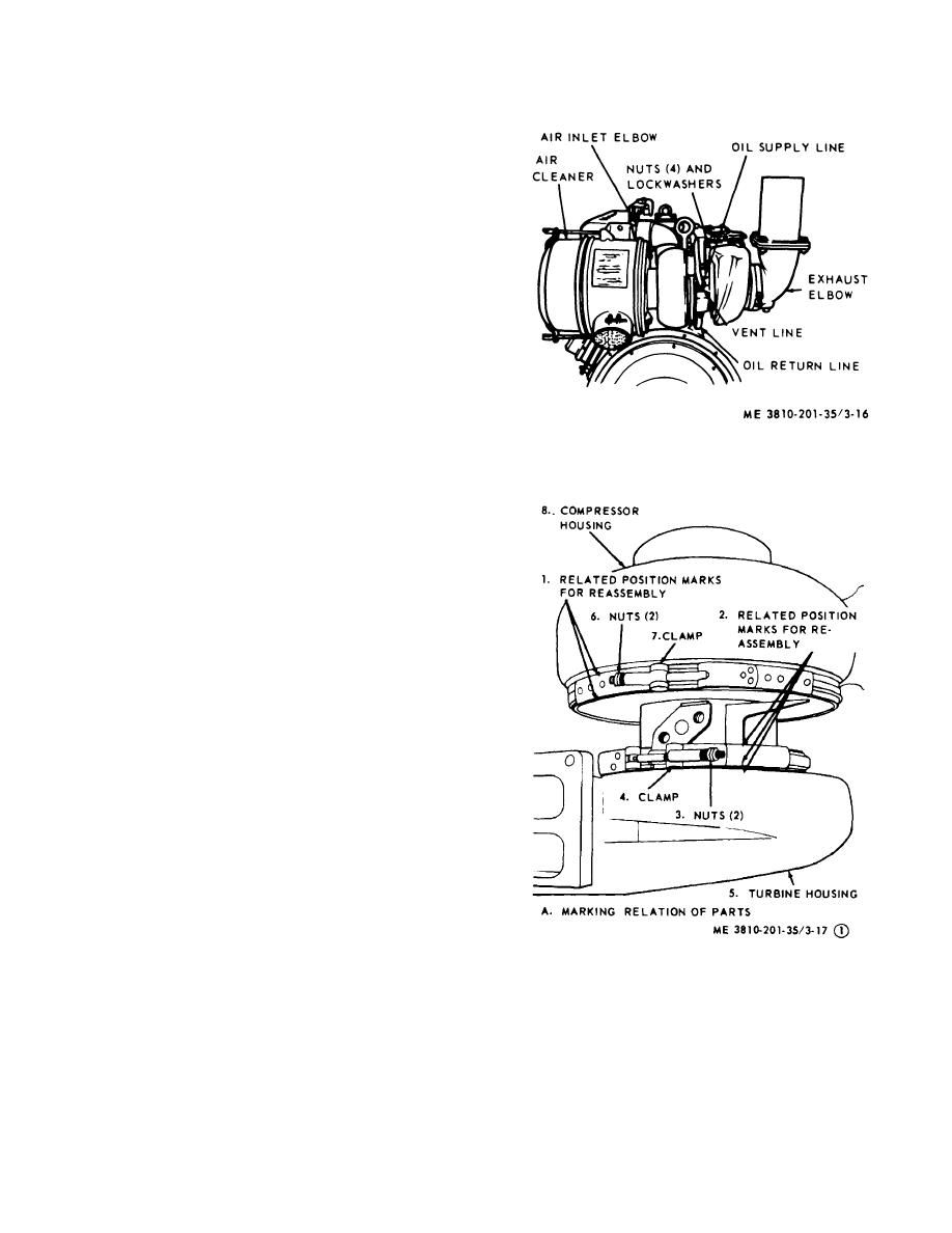
Figure 3-16. Turbocharger, removal and installation.
(e) Inspect housing for breaks, cracks,
corrosion, or warpage.
Check threaded areas for
marred, stripped, or damaged threads.
Replace a
defective housing.
Replace defective mounting
hardware.
3-15. Turbocharger for Engine Model D333TA
a. General. This engine uses an exhaust gas
driven turbocharger. Energy ordinarily lost by the diesel
engine exhaust is used to drive the turbocharger. As the
engine starts, flow of gases from exhaust manifold is
directed to turbine wheel.
The turbine wheel and
impeller are mounted on a common shaft. Gases
(Figure 3-17 Sheet 1 of 10)
passing over turbine wheel force it and impeller to rotate,
(Figure 3-17 Sheet 2 of 10)
with used gases exhausting through outlet to exhaust
(Figure 3-17 Sheet 3 of 10)
(Figure 3-17 Sheet 4 of 10)
pipe and to the atmosphere. The impeller draws air
(Figure 3-17 Sheet 5 of 10)
through the air cleaner, compresses the air, then forces
(Figure 3-17 Sheet 6 of 10)
it through aftercooler to the inlet manifold and cylinder
(Figure 3-17 Sheet 7 of 10)
(Figure 3-17 Sheet 8 of 10)
head. The air inlet manifold is cast as an integral part of
(Figure 3-17 Sheet 9 of 10)
cylinder head (left side). The lower half of aftercooler
(Figure 3-17 Sheet 10 of 10)
core is enclosed by this portion of the head while the
upper half of core is housed by a cover.
The
turbocharger air outlet is connected to an opening at rear
of aftercooler by an elbow.
b. Removal and Installation.
(1) Remove exhaust elbow and air cleaner (TM
5-3810-206-12).
(2) Disconnect vent line, oil supply line, and oil
return line then plug lines and cover ports.
Figure 3-17. Turbocharger details (sheet 1 of 10).
(3) Remove the four nuts and lockwashers that
secure turbine housing to exhaust manifold, then remove
turbocharger from air inlet elbow and engine.
3-19


