TM 5-3810-206-35
(3) Lubricate shaft and position rings. Place
Lubrication, unless otherwise specified, should be clean,
clamp over turbine housing. Install bearing housing
light oil OE 10.
assembly over shaft and lower to assembly position. Do
not force; if rings do not enter bore easily remove
(1) Clamp turbine housing in vise or fixture.
housing and re-position rings on shaft.
Install nozzle ring in housing. Place turbine wheel and
(4) Align assembly marks and clamp (sheet 1 of
shaft assembly with shaft upright in housing. Place
piston ring expander sleeve (sheet 6 of fig. 2-1) over
base grease to clamp threads and face of nut. Install
shaft. Install a new piston seal, sliding seal over sleeve
and torque nut to 10 ft-lb.
into groove. Remove sleeve. Position OD of rings
(5) Assemble parts (sheet 6 of fig. 3-17)
concentric with shaft, and with gaps 180 apart.
aligning bolt holes as each part is assembled in following
(2) Sub-assemble bearing housing as follows:
order.
(a) Install turbine back plate (sheet 8 of fig.
(a) Lubricate and install bearing in
compressor end bore.
with flat side of ring resting against back plate.
(b) Place spacer on bearing housing.
(b) With compressor end of housing up,
(c) Install thrust ring and spacer sleeve.
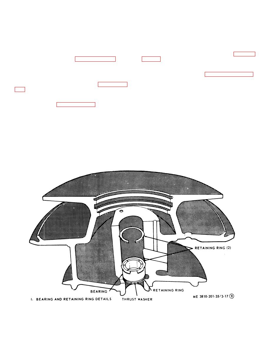
install retaining ring (sheet 9 of fig. 3-17) with flat side of
(d) Install thrust bearing with oil passage
ring facing upward.
Install bearing thrustwasher.
hole facing retainer spacer. Lubricate thrust face on
Lubricate and install bearing. Install two retaining rings
thrust bearing only.
with fiat side of rings facing bearings.
(e) Install thrust ring.
(f) Place oil deflector over thrust bearing.
Note. Use pliers to install retaining
(g) Install three lock plates and three
rings. Compress rings sufficiently to
capscrews. Torque capscrews to 5 ft-lb.
prevent their ends from scoring bore.
(h) Lock screws in place. Lockplate tangs
Make certain retaining rings are
must be locked tight against o.d. of oil deflector and
secure in grooves.
heads of capscrews.
Figure 3-17. Turbocharger details (sheet 9 of 10).
3-24


