TM 5-3810-206-35
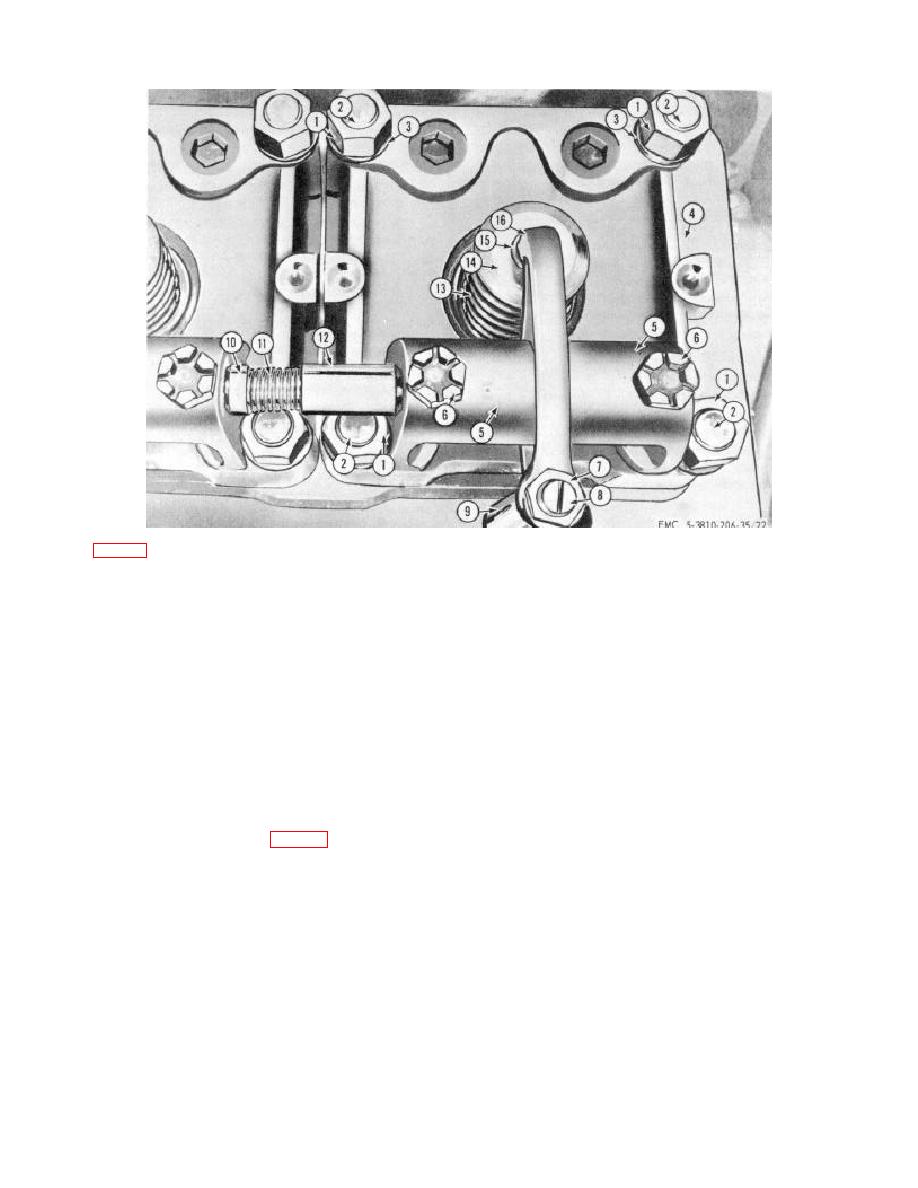
KEY to fig. 3-42:
1
Nut (24 rqr)
7
Locknut (6 rqr)
12 Sleeve (5 rqr)
2
Stud (24 rqr)
8
Adjustment screw (6 rqr)
13 Valve spring (6 rqr)
3
Lockwasher (24 rqr)
9
Pushrod (6 rqr)
14 Cap (6 rqr)
4
Cylinder head (6 rqr)
10
Plug (5 rqr)
15 Valve keeper (12 rqr)
5
Rocker arm support (12 rqr)
11
Spring (5 rqr)
16 Rocker arm (6 rqr)
6
Locknut, special (12 rqr)
Figure 3-42. Valve rocker arm, installed view.
(4) Slide plug (10) into sleeve (12) against
(11) Remove pushrod socket (14) and lever
tension of spring (11), then lift rocker arm (16), shaft and
socket (15).
supports (5) off cylinder head (4) as an assembly.
(12) Remove screw (27) and pin (18) from cam
Remove plug (10) and spring (11).
lever (16) and lever support (22). Remove cam lever
(5) Repeat steps (2) through (4) as required to
(16) from support (22).
remove remaining rocker arms.
(13) Remove pin (17) from cam lever (16), then
(6) Lift pushrods (9) out of block.
slide cam roller (26) out of cam lever (16).
(7) Remove support (9, fig. 3-43) from each end
(14) Remove nut (24), lockwasher (23), cover
of shaft (7). Slide rocker arm (6) off of shaft (7).
(22), gasket (21), pin (25), and stud (20) from cam cover
(8) Remove nut (5) and adjusting screw (11)
(22).
from rocker arm (6).
(15) Install by reversing the procedure of steps
(1) through (14) above.
b. Cleaning, Inspection, and Repair.
Note.
The sleeve bearing (4) is
(1) Clean all parts and dry thoroughly before
pressed into rocker arm (6) and
inspecting or installing the component.
should not be removed unless
(2) Inspect all parts for wear or damage.
replacement is required.
Inspect sleeve bearing for scoring, shaft and pushrod for
(9) Press bearing (4) out of rocker arms as
straightness, and spring sockets for
required.
(10) Remove cam spring socket (12) from
pushrod (13).
3-52


